Douglas XB-42 Mixmaster
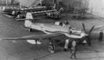
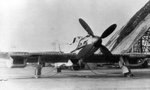
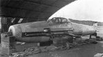
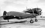
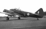
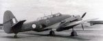
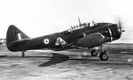
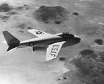
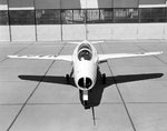
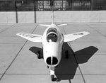
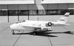
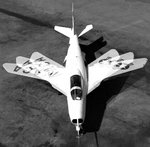
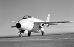
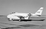
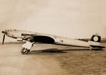
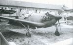
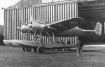
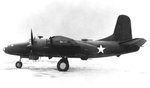
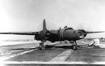
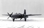
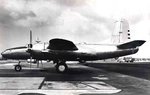
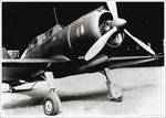
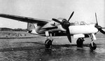
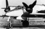
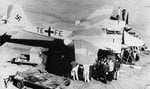
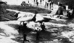
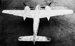
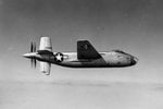
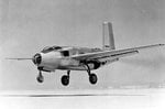
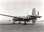
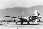
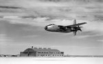
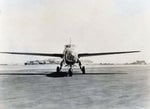
In 1943 the Douglas XB-42 project was designed to create a twin-engined bomber having a maximum speed in excess of 400 mph and capable of carrying a bombload of 2000 pounds to targets within a 2000-mile radius. This aircraft was envisaged to be an attack aircraft, but the USAAF changed its designation from XA-42 to XB-42 with the view that this bomber would be a potential substitute for the Boeing B-29 (if the Boeing project became hung up in development). The XB-42 bomber was unique in that both of its engines were located inside of the fuselage (turning a pair of contra-rotating propellers in the tail), which allowed the wing to have a clean unfettered design. The aircraft had a crew of three, and was armed with a turret contained two .50 caliber machine guns in the trailing edge of each wing. The first prototype flew in May 1944, and proved to have outstanding performance. Its top speed was over 400 mph, which was comparable to the fast British Mosquito, but the XB-42 carried twice the maximum bombload, and was better armed. Development continued until December 1945, at which time it was decided not to produce the B-42, due to the fact that jet-powered bombers were already on the drawing boards. The second prototype was modified to have turbojets under the wings for testing purposes, and was re-designated XB-42A. The project was finally canceled in 1948, with the sole-remaining example being turned over to the National Air and Space Museum in 1949. The final legacy of this project was a redesigned version with the jet engines placed inside of the fuselage, designated the XB-43.
In 1943 the Douglas XB-42 project was designed to create a twin-engined bomber having a maximum speed in excess of 400 mph and capable of carrying a bombload of 2000 pounds to targets within a 2000-mile radius. This aircraft was envisaged to be an attack aircraft, but the USAAF changed its designation from XA-42 to XB-42 with the view that this bomber would be a potential substitute for the Boeing B-29 (if the Boeing project became hung up in development). The XB-42 bomber was unique in that both of its engines were located inside of the fuselage (turning a pair of contra-rotating propellers in the tail), which allowed the wing to have a clean unfettered design. The aircraft had a crew of three, and was armed with a turret contained two .50 caliber machine guns in the trailing edge of each wing. The first prototype flew in May 1944, and proved to have outstanding performance. Its top speed was over 400 mph, which was comparable to the fast British Mosquito, but the XB-42 carried twice the maximum bombload, and was better armed. Development continued until December 1945, at which time it was decided not to produce the B-42, due to the fact that jet-powered bombers were already on the drawing boards. The second prototype was modified to have turbojets under the wings for testing purposes, and was re-designated XB-42A. The project was finally canceled in 1948, with the sole-remaining example being turned over to the National Air and Space Museum in 1949. The final legacy of this project was a redesigned version with the jet engines placed inside of the fuselage, designated the XB-43.
Attachments
Last edited: