On superchargers, Mikulins, Klimovs, Jumos, etc (1 Viewer)

Ad: This forum contains affiliate links to products on Amazon and eBay. More information in Terms and rules

tomo pauk

Creator of Interesting Threads
13,800
4,332
Apr 3, 2008
An issue raised above the shape of Jumo 213 power curve, both here and at Tony Williams' forum, made me dwell a bit about things mentioned in the title. Like I need any pretext...
One member in each forum commented that power curve should begin, for a choosen power setting, from, say, 1500 HP, and increase until the full throttle height (say, 1600 HP at that altitude). The power curves for the Jumo 213 engines (all of them) 'behave' different - they start from, say, 1700 HP and than slowly decline until full throttle height, then power sharply declines until the supercharger engages next speed. The members commented that power graphs were Jumo's fabrications, since they defy laws of physics.
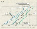
At the graph attached, the power for a chosen setting (Steig Kampfleistung) starts from 1600 PS, falling just a bit until the 1st full throttle height is reached (circled, at around 2 km), then sharply falling until supercharger is in second gear (at about 2.5 km), then again slightly falling until ~5.5 km (circled, 2nd full throttle height). The members argued that, for same setting, the powers should started from lower values, depicted here with red lines.

Jumo-213A.JPG


At Tony's forum, another member explained the matter (here, last post):
The 213 had an elaborate variable air inlet comprising "a fan-like series of eleven blades mounted in the supercharger inlet casing ... These blades movable about their axis, the movement being automatically controlled."

At yet another forum (AEHS forum, here, last post), it was stated this:
BTW, any update on the status of the Russian Piston Engine book? I hope it has ample coverage of Mikulin´s AM series. Not only it is the only series produced aero engine of the time with variable geometry blower inlet with the Jumo 213 (the latter copied the former), it seems also to be the only series produced DOHC aero engine of the war.

So I started some digging...
 
The manuals from avialogs.com were most helpful here (re. Jumo-213A, here), and the parts list for the Jumo-213A can be downloaded from cockpitinstrumente.de site. From this manual, pg.42, we can get this picture:

pg42.JPG


The 'leitschaufeln (verstellbar)' wording means 'guide vanes (adjustable)'. After the air passes through the vanes, it 'encounters' compressor blades.
There were total of 11 blades (item no. 39 in the next pic), their axles located between and held together by a suitably shaped part of housing and a circular element (item no. 10). The vanes have dented circular segments (item no. 27), that are steered by a crown-shaped circular element (item no. 23). Picture is taken from the parts list, the compressor part of the list starts from pg. 208.

blades.JPG


In the next pic, among other stuff, please note how the guide vane no.1 (Drallschaufell Nr .1) is set against the crown shaped circular element (Kegelrad (Zankrantz)). The vane has movement of 90 deg, looking by that picture.

blades2.JPG
 
Thanks. More to come :)

The caption on the bottom of the last picture reads, roughly:
When in 'open' position, the guide vanes are set at 3 deg (+- 1 deg) against the supercharger wheels axis. The vanes, in that position, are set in same direction as the impeller rotates.

The position is depicted in the illustration in the upper left part of the last picture above.
 
Last edited:
In the last picture of post #2 here, we can see the additional dented segment (13 teeth, if Ive counted right) attached to the full-circle crown-shaped item by two screws. It serves the purpose to rotate back and forth the crown-shaped item. It is powered (via a lever, a piston pin, shaft and a circular dented element of it's own) by a piston (named 'Kolben des füllungverstärkers') . Picture:

jumo213compr.JPG


The crown-shaped (Kegelrad-zankrantz) item is shown, too, along with it's connection with one of the the guide vanes (Leitschaufel).
The next pic should contribute to the topic, we can see how the piston adjusts the vanes at the end:

Jumo-213A1comp.JPG


The photo of the intake is attached next. Note the guide vanes (silver color) and impeller blades (white color), also note that vanes' axles are 'sandwithched' between two circular-shaped parts:

JumoComp.JPG


The Jumo-213E received two-stage 3-speed supercharger, and the guide vanes were also changed, at least in shape and location (left is 1-stage, right is 2-stage compressor):

2stg.JPG
 
Seems that German name for this apparatus was named as 'enhancer of loading', or 'enhancer of supercharging', in a more liberal translation of the 'Fullungverstaerker'.

Now, back at the people that supposedly invented the thing. The inventor's last name seems to be Polikovsky, at least if we go by this excerpt:

Эти двигатели были выпущены относительно небольшой серией, поскольку самолеты ТБ-7 строились с низким темпом. Число модернизированных бомбардировщиков ТБ-3, где АМ-34ФРН также нашел применение, было невелико. В то же время конструкцию мотора пришлось существенно изменить. В связи с увеличением мощности и частоты вращения многие детали были усилены, переделана система смазки, пересмотрена конструкция шатунов. Мотор оснащался односкоростным нагнетателем ФН-35. На входе в него применили направляющий аппарат с поворотными лопатками Поликовского, что значительно улучшило высотные характеристики и увеличило на 90...100 л.с. эффективную мощность у земли и на высотах ниже расчетной.

...or, with help of Google translator, my comments in square brackets:

These engines were produced by a series of relatively small , because TB-7 aircraft were built with a low rate . Number modernized bombers TB-3 , where the AM 34FRN also found application was small. At the same time the design of the motor had to significantly change . With the increase in power and speed , many details have been strengthened, modified lubrication system, revised construction rods. Motor equipped with a single-speed supercharger FN- 35. At its inlet guide vanes used with rotary blades [designed by] Polikovsky , which greatly improved high-altitude performance , and increased by 90 to 100 hp ... effective power at the ground and at altitudes lower than estimated [?? - 'lower than full throttle height', not 'lower than estimated'].

'Rасчетная высота' would mean 'rated height', or 'full throttle height'. Excerpt taken from here.

Now we can take a look at the shape of power vs. altitude graphs. A neatly colored chart I've nicked from another site, the term 'боевой рeжим' can be translated as 'combat emergency regime', or describes as an equivalent for German term 'Notleistung'. Didn't cross checked values for the DB-603AM, though. For a good measure, I've added the lines (black) for two engines that were produced only in small quantities, namely the AM-35 and AM-37. Please note how the M-34FRN gained, vs. the M-34N and M-34RN, circa 200 HP at lower altitudes, and 100 HP more above 3.5 km. Also note the smoother power graph for engines with Polikovsky's vanes, ie. starting with M-34FRN. 'F' means 'forsirovany' (~highly boosted), 'R' (cyrilic P) means it has reduction gear, 'N' (cyrilic H) means it has supercharger.
Piston engines designed by Mikulin received prefix AM from late 30s/early 40s on; 'M' meant simply 'motor', 'AM' meant Alexandar Mikulin. In Germany, OTOH, AM meant something else :)

mikulin-all2.JPG
 
To continue with the saga. The earliest drawing of supercharger I was able to find, that is employing the inlet guide vanes by Polikovsky, is from AM-38. On the picture just under, we can see compressor's casing, cover, complete set of guide vanes in their casing/support, then, in next row, some springs, two parts of supercharger impeller, and a single guide vane (note the dented segment):

compress 4.JPG


The partial cutaway of the complete supercharger, visible are the vanes and two-part impeller:

compress 3.JPG


Another cutaway. The item no. 36 is some kind of lever, and only one vane has it? Connected to other vanes how, via item no.16? Inlet vane(s) is (are) item no. 6.

compress 1.JPG
 
Soviets seem to love not to reveal much data about their superchargers. Either that, or I really need to learn Russian language ;)
The diameter of supercharger in AM-35A was 275mm (from here), AM-38 and AM-38F were of same diameter? For the AM-37 the supercharger grew to 285mm, the intecooler was installed after the supercharger and before carburetors. The supercharger drive ratio is 14.6:1 (in US terminology) for the AM-35A, and 11.05:1 for the AM-38, per this table:

table AM.JPG


Interestingly enough, the Mikulins V-12 used the master+articulated rod assemblies, not fork+blade for their crank pins. That gave different stroke values for pistons at left and right blocks - 190 mm and 196.77 mm respectively.
Vs. the AM-35A, the AM-38 used a decreased compression ratio - from 7:1 to 6.8:1, further reduced for the AM-38F to 6:1. Manifold pressures were increased (with greater RPM that meant more power down low), at cost of altitude performance.
 
Here is an excerpt from 'The TsAGI' book, pg. 172 and 173, about the AM-38F:

F.JPG


That reads something along this lines:
In an Il-2 two-seater, in early 1942, the AM-38F (forsirovany) engine was installed, that, compared with AM-38, have had less power at altitude, but the take-off power was increased by 100 HP. The take off regime was allowed for 10 minutes, at altitudes between 0-1.5 km ('combat regime'). In order to allow use of lower octane fuel (in that time, it was problematic to acquire high-octane fuel), the compression ratio was decreased (now 6.0:1 instead of 6.8:1), allowed RPM were increased in take off regime (2350 instead of 2150), manifold pressure was, at lower altitudes, also increased. Diameter of the impeller was also decreased, compared with AM-38.

For a more clear picture, please open it separately:

AMs.JPG
 
Picture of the AM-38F, guide vanes are easy to spot:

http://www.aircraftengine.cz/Kosice/slides/Mikulin%20AM-38F%20(2).jpg

Guide vanes from AM-42, with detail showing part of vanes' control mechanism. Note that caption refers to the apparatus as 'Polikovsky's guide vanes'.

42vanes.JPG


The AM-42's crankshaft was outfitted with counterweights, so the engine was able to turn greater RPM, up to 2500. The compression ratio was also reduced, to 5.5:1, so greater boost was allowed. All that, combined with neccessarry bulking up of different parts of the engine, enabled circa 300-350 HP more than AM-38F. Please look at the table in post #9 here and in the power chart. Not everything went smooth with development of the AM-42, Russian-language Wikipedia (can be translated) lists a number of defects that needed to be addressed prior the engine passed Government's tests.
 
More excellent work. :thumbup: :salute:

I believe (but could very well be wrong) that the guide vanes on the AM series of engines also acted as the 'throttle plate' and controlled quantity of air entering as well as speed and angle that the air hit the impeller.

I am not sure if that was true of the Jumo guide vanes, they would need enough travel (arc) and the proper shape to close off the entry or nearly so.
 
Thanks.

The carburetors on the Mikulins did emlpoy the throttle plates (one per carb, of course). Carburetor from AM-38; the throttle plate should be the circular item near the top of the 'tube' of carburetor:

carb1.JPG


The shaft for controlling the throttle plate angle can be discerned at lower cutaway, above the caption.

Next, the carburetor for the AM-42. Throttle plate should be item no. 3. Note the four arrows, showing direction of air from compressor:

carb42.JPG


For the Jumo-213A seem you're right that vanes doubled as throttle plate, a more complete look at the manual should give the definitive answer.

added: FWIW, I've waded though the Jumo-213A manual, didn't found the throttle plate. Plus, the power graph for, eg. 1st speed of the Jumo-213A and AM-38 differs a bit. From full throttle height towards the SL, the power is always slightly increased in case of 213A; inc case of AM-38, the power gets slightly higher from FTH (at 1650m) down to 1 km, but then is slightly lower, from ~1 km down. Looks indeed like the throttle plate is much less an efficient thing in controlling the boost, than the inlet guide vanes.
 
Last edited:
Perhaps the throttle plates worked together? Supercharger inlet vanes only opened in proportion to throttle plates in the carburetor so the supercharger casing was not over pressurized at less than full throttle height with the carburetors acting as "limiting valves"?

Just guessing? American/British engines had the carbs before the supercharger and limited the amount of air reaching the supercharger. This may have meant some 'pumping losses' at part throttle but a wide open inlet at low altitude might mean the supercharger is running/churning much more air than is being let by the limiting valve/carb?
 
You're probably right on both accounts. I do have a complete manual for the AM-42 and some illustrations for the AM-38, but my feeble command of Russian language does not give me enough confidence to try and understand how the regulation actually worked.
 
I was not overly succesful in finding out how much the AM-35A was suitable for over-boosting, ie. the equivalent of US 'war emergency power'. Going by this article (can be translated): http://engine.aviaport.ru/issues/13/page46.html):

Мотор АМ-35А в конце 1940 г. был запущен в серию. На расчетной высоте АМ-35А имел номинальную мощность 1200 л.с., а максимальная мощность в течение 20 мин. на высоте 4750 м составляла 1400 л.с. Этот результат был выдающимся для 1940 г.

Meaning, with help of google translator:

AM-35A engine at the end of 1940 was put into production. On the rated height, the AM-35A have had a nominal power of 1200 hp and maximum power, for 20 min, at an altitude of 4750 m was 1400 hp. This result has been outstanding for 1940.

The 20 min for overboosting seem to me like a way too long time. Soviets used 95 oct fuel for their 'new' engines, like M-105 and like. Also it is questionable whether Soviets started over-boosting their engines prior 1942; for the Klimov's engines it was the bulked-up VK-105PF in mid 1942 that was 1st allowed for over-boost.

The another chart shows, among others, the I-225 (with AM-35A on board). The dashed speed line is captioned with 'forsazh' - ie. emergency power. Over-boosting? The max altitude for 'forsazh', without ram, should be at circa 2-2.5 km? Also, the graph for the MiG-3 with AM-38 should be somewhat smoother, like the one for Il-1 (armored fighter, sibling of Il-2).
Seems like the M-71 (in I-185) and M-71 has 3 power peaks. Engine in the experimental aircraft '120' is ASh-83 (modification of the ASh-82 line), the I-220 have had the AM-39 installed.
Please open the image separately, for greater resolution.
 

Attachments

  • exp.JPG
    exp.JPG
    60.4 KB · Views: 521
Last edited:
Seems like that Polikovksy's giude vanes were also incorporated in the DB-605L and DB-603L, the two stage engines. Going by this link , the member named 'grifon' makes some convincing posts. Unfortunately, the ocean of flag-waving might hamper the reading in that thread.
 
Hi Tomo,

In your post 9 above, I calculated the MEP, BMEP, and specific power for these engines. I assumed all ratings were at the only rpm shown.

The row you think is MEP is not and neither is the specific power. I don't know what they are, but the specific power isn't hp/lb or kW/kg and the MEP / BMEP is not psi or Bar. I really didn't expect them to be SAE units, but thought maybe they'd be standard metric units. I tried cv/kg and the number goes the wrong way ... it needs to be less and is, in fact, more. Bar is directly related to kPa, so it isn't anything to do with Pa / kPa or Bar.

Now I'm curious ... maybe it's related to the number of hot babes per square ski slope in Sochi during the Olympics.
 
I'm not aware of any of your calculations in post #9 - they are all Soviet ones. As for my caption 'Specific power', it is for the category that expressed in kilograms per (metric) horse power, ie. dry weight of enginedivided by power. Unfortunately, the Soviets did not stated the power-to-weight ratio, ie. HP per unit of mass, that should be a reciprocial value.
As for MEP, you will notice the questionmark after that caption, that say 'I'm not sure'. At any rate, the value seem to be 'kilogram x second / square centimeter', but I'll accept a well-described axplanation of what the table's authors meant.
 
Well if we have kg-s/cm^2, we can go from there.

Actually I went with standard SAE and metric units so I could compare these engines with all the other engines I have these numbers for. I don't care which unit system I use because conversion among them isn;t too difficult. I simply don't read Crylic.

I notice the German engine being compared, the DB 603 AM, was a relatively short-lived one in Luftwaffe service. Maybe the authors wanted to live longer in Stalin's purges if their numbers looked better. And, these Soviet engines look pretty good on paper and operated in conditions that grounded most other ALlied (and most German) engines, so whether or not they had a long time between overhaul, they gave good service in the intended environment.

Wish we has a few around today to hear them run alongsode the Merlins, Allison, etc. Wish we has some running Italian engines around other than Italian auto engines. Ferrari's sound wonderful ... until you have buy the parts. I had three friends with Ferraris and they all loved them while simultaneously hating the expense of them, sort of like owning a Porsche.

Do you have any similar charts on Klimov and/or Shvetsov engines? I have SOME of the vitals, but not all. For instance I have power and sometimes rpm, but no manifold pressure data. Finding data on Soviet engines of WWII isn't like finding specs on a Merlin! That's for sure ...
 
An entusiast has translated lots of engine and aircraft tables on Spanish (so it can be easy to translate), along with aircraft graphs and posted that stuff here. I do have the graphs, the Klimov's are posted here before, but I'll post them in this thread again.
The TsAGI book was published in1992, so the auhors didn't had to worry from Stalin's wrath. He would probably harm those that prommised, but didn't delivered. With that said, people should NOT use the data and the graphs for non-USSR engines planes from the book as reference, most of the times it gives lower values than it was in reality.
In case you need to have something transcribed from cyrilic, I can give it a try.
 

Users who are viewing this thread

Back