Navigation
Install the app
How to install the app on iOS
Follow along with the video below to see how to install our site as a web app on your home screen.
Note: This feature may not be available in some browsers.
More options
You are using an out of date browser. It may not display this or other websites correctly.
You should upgrade or use an alternative browser.
You should upgrade or use an alternative browser.
K-14 gunsight
- Thread starter corbo
- Start date
Ad: This forum contains affiliate links to products on Amazon and eBay. More information in Terms and rules
More options
Who Replied?corbo said:Hello,
Can anyone help me with the details about the way K-14 gunsight worked on P-51 Mustang fighter? Thanks and regards. Corbo, Naples, Italy
The K-14, MK. 18 (USN version), and Ferranti (British version) gyro computing gunsights used a gyro to measure rate of turn to give a lead compensation which was applied to the reflector gunsight. The pilot preset the gunsight with the wingspan of the target. He then used a twist knob on the throttle handle which would adjust the size of a sighting ring (reflected on the sighting panel) called a recticle (this varied in layout, but usually consisted of six diamond shapes) to the target wingspan. The further away the target, the smaller the ring. Matching the ring size to the target wingspan gave the range, which was fed into the analog computer to give the required lead compensation. When the target was in the ring the guns were aimed where the target would be when the bullets got to the targeted range.
So to use the system, the pilot put the ring on the target and held it there while shooting. It eliminated guessing how much lead was required - most pilots tended to grossly underestimate the required lead.
By Korea the human element had been removed, instead of twisting a knob a radar ranging system input the distance component.
Note: when engaging in aerobatics the gyro's needed to be caged. If the pilot forgot to do so the system would be damaged and useless. When the gyros were caged, the system acted as a simple reflector gunsight. So the pilot had to be well trained to cage and uncage the gyros during combat.
=S=
Lunatic
- Thread starter
- #3
Hello,
Thank you so much, Lunatic. Perchance, could you help me also with the way A-4 radar gun sight worked on F-86E? Regards.
Can anyone help me with the details about the way K-14 gun sight worked on P-51 Mustang fighter? Thanks and regards. Corbo, Naples, Italy[/quote]
The K-14, MK. 18 (USN version), and Ferranti (British version) gyro computing gun sights used a gyro to measure rate of turn to give a lead compensation which was applied to the reflector gun sight. The pilot preset the gun sight with the wingspan of the target. He then used a twist knob on the throttle handle which would adjust the size of a sighting ring (reflected on the sighting panel) called a reticule (this varied in layout, but usually consisted of six diamond shapes) to the target wingspan. The further away the target, the smaller the ring. Matching the ring size to the target wingspan gave the range, which was fed into the analog computer to give the required lead compensation. When the target was in the ring the guns were aimed where the target would be when the bullets got to the targeted range.
So to use the system, the pilot put the ring on the target and held it there while shooting. It eliminated guessing how much lead was required - most pilots tended to grossly underestimate the required lead.
By Korea the human element had been removed, instead of twisting a knob a radar ranging system input the distance component.
Note: when engaging in aerobatics the gyro's needed to be caged. If the pilot forgot to do so the system would be damaged and useless. When the gyros were caged, the system acted as a simple reflector gun sight. So the pilot had to be well trained to cage and uncage the gyros during combat.
=S=
Lunatic[/quote]
JonJGoldberg
Airman 1st Class
- Thread starter
- #5
Thank you Goldberg,
My residual question: In the gyro-computing mode, how could the P-51 pilot know that he was within firing range, once he had adjusted the 6 diamonds around the target, by rotating the throttle grip, and tracked the target for the required 1 second? Had the range to be somehow fed in beforehand, also in the "gyro" mode? Thanks. Corbo
My residual question: In the gyro-computing mode, how could the P-51 pilot know that he was within firing range, once he had adjusted the 6 diamonds around the target, by rotating the throttle grip, and tracked the target for the required 1 second? Had the range to be somehow fed in beforehand, also in the "gyro" mode? Thanks. Corbo
JonJGoldberg
Airman 1st Class
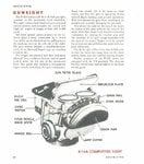
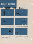
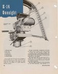
These instructions are from a P-47's K-14. The instructions are much more clear... Hope it helps.
The manual was downloaded from a web site that is no longer...
The manual was downloaded from a web site that is no longer...
Attachments
- Thread starter
- #7
- Thread starter
- #8
Hi everybody,
Sorry to be here again, but I have one more question. Th P-47/K-14 manual says that "...when the separation of the fixed cross and the dot shows that a long lead, around 85-100 mils, is being allowed...". I seem to know that "normal" circle diameter on majority of sight guns is 50 mils, so how can a 85-100 mils lead be shown on reflector glass? Thanks once more.[/u]
Sorry to be here again, but I have one more question. Th P-47/K-14 manual says that "...when the separation of the fixed cross and the dot shows that a long lead, around 85-100 mils, is being allowed...". I seem to know that "normal" circle diameter on majority of sight guns is 50 mils, so how can a 85-100 mils lead be shown on reflector glass? Thanks once more.[/u]
corbo said:Hi everybody,
Sorry to be here again, but I have one more question. Th P-47/K-14 manual says that "...when the separation of the fixed cross and the dot shows that a long lead, around 85-100 mils, is being allowed...". I seem to know that "normal" circle diameter on majority of sight guns is 50 mils, so how can a 85-100 mils lead be shown on reflector glass? Thanks once more.
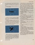
Because on the K-14 the circle diameter changes when the pilot adjusts the ranging knob on the throttle handle. What you have to realize that is not stated clearly in the above descriptions is that when in gyro mode the sight is going to move the dots on the reflector panel to adjust the sighting. By keeping the center dot on the target and bracketing it with the ranging circle, the gyro data allows the computer to calculate the lead and adjust the position of the dots. Adjusting the ranging circle gives the range, adjusting the planes orientation to keep the center dot on the target gives the course info, and if both these things are done properly, the bullets will hit the target.
So if the shooter is flying due North to start with and the target is flying due East (to the right), at 2400 feet the shooter can set the circle at the targets span (as described, by putting the tail on the circle), hold the dot on the targets cockpit for one second while adjusting the ranging circle to account for the closing distance, and fire and score. The pilot onlys need keep that dot on the target's cockpit and adjust the ranging knob, the computer calculates the target's vector and shifts the recticle to the left to achieve the required lead.
The radar version used in the Korean war (and beyond) used a radar ranging system instead of the pilot manually controlling ranging via the twist knob.
=S=
Lunatic
- Thread starter
- #10
Thank you again Lunatic,
Your addition threw more light on the problem, but I fear I didn't make me clear enough: when I spoke of the "circle" diameter being "normally" 50 mils, I referred to the overall span of the gun sight - sort of its horizon - not to the targets size circle, which can be adjusted by rotating the throttle grip. Was I wright in my assumption that such overall span is 50 mils, or does this overall diameter - and corresponding mils -vary according to range, in which case a separation of 85-100 mils can be quite understandable? Thanks a lot. Regards.
Your addition threw more light on the problem, but I fear I didn't make me clear enough: when I spoke of the "circle" diameter being "normally" 50 mils, I referred to the overall span of the gun sight - sort of its horizon - not to the targets size circle, which can be adjusted by rotating the throttle grip. Was I wright in my assumption that such overall span is 50 mils, or does this overall diameter - and corresponding mils -vary according to range, in which case a separation of 85-100 mils can be quite understandable? Thanks a lot. Regards.
Hello,
I know nothing about the A4 sight on F86E, but I know a lot about the E-4 firecontrol system used on the F86D Super sabre.
The system consisted of a radar covered by a black radome over the air intake in the nose of the aircraft, a flight-data computer, a fire-control computer and in the cockpit a radar scope ( E-type ) and a joystick used to control the radar antenna during lock-on to the target. The system could operate in 3 modes: Search mode, lock-on mode and attack-mode.
In the search mode the antenna searched the horizon from side to side. When the pilot got a target on the scope he would switch the system to lock-on mode by pressing a knop on the joystick. In lock-on mode the antenna was controlled horrizontally and vertically by the joystick. When the pilot had aimed the antenna at the selected target, he would use a thumbwheel on the joystick to move a marker along the sweep on the scope. When the marker was placed over the target, the system would lock-on and switch to attack-mode.
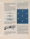
In attack-mode the radar would automatically track the target in azimuth, elevation and range (the antenna was locked to the target). The scope would now show steering information instead of radar information. This information consisted of:
1) time until firing the weapons (a big circle, the size of which indicated the remaining time)
2) the rate at which the aircraft was closing in on the target ( a gap in the big circle. 12 o'clock = 0 kts, 3 o'clock = 100 kts etc. )
3) stearing information (a small circle and a litle cross which had to be centered within each other) The pilot had to maneuver the aircraft in the same direction the litle cross was moving on the scope.
4) Firing information. ( A big cross on the scope ). If the pilot had the trigger pulled at this time, the weapons woud be fired. If the weapons were 2,75" rockets, the rocket-pod placed in fuselage would lower automatically and the rockets would be fired.
5) Collision avoidence info. ( 2 circles forming the letter 8 ) the pilot had to break away in the direction given by the "8" to awoid coliding with debries from the target.
nop
The K-14, MK. 18 (USN version), and Ferranti (British version) gyro computing gun sights used a gyro to measure rate of turn to give a lead compensation which was applied to the reflector gun sight. The pilot preset the gun sight with the wingspan of the target. He then used a twist knob on the throttle handle which would adjust the size of a sighting ring (reflected on the sighting panel) called a reticule (this varied in layout, but usually consisted of six diamond shapes) to the target wingspan. The further away the target, the smaller the ring. Matching the ring size to the target wingspan gave the range, which was fed into the analog computer to give the required lead compensation. When the target was in the ring the guns were aimed where the target would be when the bullets got to the targeted range.
So to use the system, the pilot put the ring on the target and held it there while shooting. It eliminated guessing how much lead was required - most pilots tended to grossly underestimate the required lead.
By Korea the human element had been removed, instead of twisting a knob a radar ranging system input the distance component.
Note: when engaging in aerobatics the gyro's needed to be caged. If the pilot forgot to do so the system would be damaged and useless. When the gyros were caged, the system acted as a simple reflector gun sight. So the pilot had to be well trained to cage and uncage the gyros during combat.
=S=
I know nothing about the A4 sight on F86E, but I know a lot about the E-4 firecontrol system used on the F86D Super sabre.
The system consisted of a radar covered by a black radome over the air intake in the nose of the aircraft, a flight-data computer, a fire-control computer and in the cockpit a radar scope ( E-type ) and a joystick used to control the radar antenna during lock-on to the target. The system could operate in 3 modes: Search mode, lock-on mode and attack-mode.
In the search mode the antenna searched the horizon from side to side. When the pilot got a target on the scope he would switch the system to lock-on mode by pressing a knop on the joystick. In lock-on mode the antenna was controlled horrizontally and vertically by the joystick. When the pilot had aimed the antenna at the selected target, he would use a thumbwheel on the joystick to move a marker along the sweep on the scope. When the marker was placed over the target, the system would lock-on and switch to attack-mode.
In attack-mode the radar would automatically track the target in azimuth, elevation and range (the antenna was locked to the target). The scope would now show steering information instead of radar information. This information consisted of:
1) time until firing the weapons (a big circle, the size of which indicated the remaining time)
2) the rate at which the aircraft was closing in on the target ( a gap in the big circle. 12 o'clock = 0 kts, 3 o'clock = 100 kts etc. )
3) stearing information (a small circle and a litle cross which had to be centered within each other) The pilot had to maneuver the aircraft in the same direction the litle cross was moving on the scope.
4) Firing information. ( A big cross on the scope ). If the pilot had the trigger pulled at this time, the weapons woud be fired. If the weapons were 2,75" rockets, the rocket-pod placed in fuselage would lower automatically and the rockets would be fired.
5) Collision avoidence info. ( 2 circles forming the letter 8 ) the pilot had to break away in the direction given by the "8" to awoid coliding with debries from the target.
nop
Hello,
Thank you so much, Lunatic. Perchance, could you help me also with the way A-4 radar gun sight worked on F-86E? Regards.
Can anyone help me with the details about the way K-14 gun sight worked on P-51 Mustang fighter? Thanks and regards. Corbo, Naples, Italy
The K-14, MK. 18 (USN version), and Ferranti (British version) gyro computing gun sights used a gyro to measure rate of turn to give a lead compensation which was applied to the reflector gun sight. The pilot preset the gun sight with the wingspan of the target. He then used a twist knob on the throttle handle which would adjust the size of a sighting ring (reflected on the sighting panel) called a reticule (this varied in layout, but usually consisted of six diamond shapes) to the target wingspan. The further away the target, the smaller the ring. Matching the ring size to the target wingspan gave the range, which was fed into the analog computer to give the required lead compensation. When the target was in the ring the guns were aimed where the target would be when the bullets got to the targeted range.
So to use the system, the pilot put the ring on the target and held it there while shooting. It eliminated guessing how much lead was required - most pilots tended to grossly underestimate the required lead.
By Korea the human element had been removed, instead of twisting a knob a radar ranging system input the distance component.
Note: when engaging in aerobatics the gyro's needed to be caged. If the pilot forgot to do so the system would be damaged and useless. When the gyros were caged, the system acted as a simple reflector gun sight. So the pilot had to be well trained to cage and uncage the gyros during combat.
=S=
Users who are viewing this thread
Total: 1 (members: 0, guests: 1)
Similar threads
- Replies
- 10
- Views
- 4K