Airframes
Benevolens Magister
DH Mosquito FBVI, coded YH-Z, serial number HR348, 21 Squadron RAF, 1944.
This aircraft was flown by my friend, American pilot Bob Kirkpatrick, who, after joining the RCAF, arrived on 21 Sqn in September 1944. On the night of December 24 - 25th, Bob was sent to bomb a bridge in the Ardennes, in Belgium, during what came to be know as 'The Battle of the Bulge'.
As he dived down to the target, "all hell broke loose", as a Panzer Battalion, hidden in the forest, opened up with everything they had! Banking to avoid the flak, Bob saw his bombs explode near to, but not on the target, and got out of there rapidly, but not before taking some hits and sustaining damage, making a forced landing in England after crossing the sea on one engine.
Bob was later to make a further emergency landing, after flying one of the FPU Mosquitos during the famous low-level attack on Gestapo HQ in Shell House, Copenhagen, in March 1945. Again hit by flak, his aircraft sustained damage to the nose, starboard engine and hydraulics and, although he was able to lower the landing gear, the aircraft was without brakes or flaps, and coasted to a halt on the runway of the first airfield Bob saw back in England, at Rackheath in Norfolk, a USAAF B24 base.
The kit used here will be the re-boxing, by Modelcraft of Canada, of the old Revell 1/32nd scale Mosquito BIV bomber, with this example being moulded in Mexico.
This kit was very kindly and generously sent to me by our very own David (vikingberserker), and I must publicly thank him once again for this very thoughtful gesture - Thanks David !
The kit arrived with a little bit of damage to the starboard nose, easily repairable, which actually aids in the preparation of the conversion, and this will take a lot of preparation before construction proper begins !
This is going to be quite a long job, as the only conversion parts which were available, by Paragon Productions, are now long out of production, and this will mean constructing a new nose from scratch, moulding a new canopy, and a lot of scratch-building and corrections. However, having used this kit many years ago, to produce a PR XVI example, I reckon the scratch-building, of the interior at least, shouldn't be too bad.
The pics show the first stage of preparation.
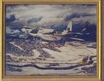
PIC 1. A painting I did for Bob back in 1996, showing his 'Mossie' over the target in the Ardennes.
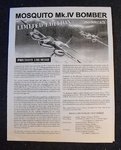
PIC 2. Kit instruction sheet.
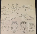
PIC 3. This is a 1/32nd scale plan I prepared, again in 1996, showing the differences between the fighter and bomber.
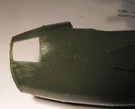
PIC 4. The damage done to the starboard fuselage half in transit.
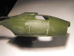
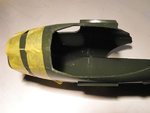
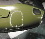
PIC 5. A tracing of the FBVI entrance hatch was made, cut out, and taped in position on the fuselage section, ready for scribing the shape of the door.
PIC 6. The nose section overlaid over the FBVI plan, showing the re-shaping required. This will be done once the fuselage is completed, using a balsa wood 'plug' and Milliput.
PIC 7. The position of the door has been scribed, using the tip of a pair of dividers.
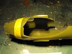
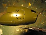
PIC 8. Holes were drilled around the periphery of the door, inside the scribed lines, to simply cutting. the outer arc of each hole can then form the required curves.
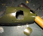
PIC 9. A razor saw and scalpel were then used to cut through the relatively thick (1.25mm) plastic, and the unwanted part removed.
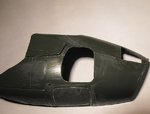
PIC 10. The cut out hatch, ready for filing and sanding to final shape. Note that the upper part of the nose cracked during the final cut, probably due to this area already being stressed after the previous damage, but this was easily repaired, and will not be seen on the finished model, especially after all the putty goes on !
Next step is to tape the fuselage halves together, and modify the shape of the cockpit opening to match the 'straight' windscreen of the fighter-bomber. A balsa 'male' mould will then be carved, checking for fit as it progresses, and a new canopy moulded from clear plastic sheet.
Apologies for such a long introductory post, and I'll post more pics as the work slowly progresses over the coming weeks ... er.... months !
This aircraft was flown by my friend, American pilot Bob Kirkpatrick, who, after joining the RCAF, arrived on 21 Sqn in September 1944. On the night of December 24 - 25th, Bob was sent to bomb a bridge in the Ardennes, in Belgium, during what came to be know as 'The Battle of the Bulge'.
As he dived down to the target, "all hell broke loose", as a Panzer Battalion, hidden in the forest, opened up with everything they had! Banking to avoid the flak, Bob saw his bombs explode near to, but not on the target, and got out of there rapidly, but not before taking some hits and sustaining damage, making a forced landing in England after crossing the sea on one engine.
Bob was later to make a further emergency landing, after flying one of the FPU Mosquitos during the famous low-level attack on Gestapo HQ in Shell House, Copenhagen, in March 1945. Again hit by flak, his aircraft sustained damage to the nose, starboard engine and hydraulics and, although he was able to lower the landing gear, the aircraft was without brakes or flaps, and coasted to a halt on the runway of the first airfield Bob saw back in England, at Rackheath in Norfolk, a USAAF B24 base.
The kit used here will be the re-boxing, by Modelcraft of Canada, of the old Revell 1/32nd scale Mosquito BIV bomber, with this example being moulded in Mexico.
This kit was very kindly and generously sent to me by our very own David (vikingberserker), and I must publicly thank him once again for this very thoughtful gesture - Thanks David !
The kit arrived with a little bit of damage to the starboard nose, easily repairable, which actually aids in the preparation of the conversion, and this will take a lot of preparation before construction proper begins !
This is going to be quite a long job, as the only conversion parts which were available, by Paragon Productions, are now long out of production, and this will mean constructing a new nose from scratch, moulding a new canopy, and a lot of scratch-building and corrections. However, having used this kit many years ago, to produce a PR XVI example, I reckon the scratch-building, of the interior at least, shouldn't be too bad.
The pics show the first stage of preparation.
PIC 1. A painting I did for Bob back in 1996, showing his 'Mossie' over the target in the Ardennes.
PIC 2. Kit instruction sheet.
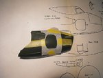
PIC 3. This is a 1/32nd scale plan I prepared, again in 1996, showing the differences between the fighter and bomber.
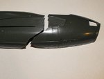
PIC 4. The damage done to the starboard fuselage half in transit.
PIC 5. A tracing of the FBVI entrance hatch was made, cut out, and taped in position on the fuselage section, ready for scribing the shape of the door.
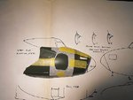
PIC 6. The nose section overlaid over the FBVI plan, showing the re-shaping required. This will be done once the fuselage is completed, using a balsa wood 'plug' and Milliput.
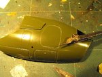
PIC 7. The position of the door has been scribed, using the tip of a pair of dividers.
PIC 8. Holes were drilled around the periphery of the door, inside the scribed lines, to simply cutting. the outer arc of each hole can then form the required curves.
PIC 9. A razor saw and scalpel were then used to cut through the relatively thick (1.25mm) plastic, and the unwanted part removed.
PIC 10. The cut out hatch, ready for filing and sanding to final shape. Note that the upper part of the nose cracked during the final cut, probably due to this area already being stressed after the previous damage, but this was easily repaired, and will not be seen on the finished model, especially after all the putty goes on !
Next step is to tape the fuselage halves together, and modify the shape of the cockpit opening to match the 'straight' windscreen of the fighter-bomber. A balsa 'male' mould will then be carved, checking for fit as it progresses, and a new canopy moulded from clear plastic sheet.
Apologies for such a long introductory post, and I'll post more pics as the work slowly progresses over the coming weeks ... er.... months !
Attachments
-
 Mossie 32 scale.jpg144.1 KB · Views: 390
 -
 Mossie 32 scale 003.jpg85 KB · Views: 366
 -
 Mossie 32 scale 011.jpg87.9 KB · Views: 377
 -
 Mossie 32 scale 002.jpg78.7 KB · Views: 383
 -
 Mossie 32 scale 004.jpg48.7 KB · Views: 389
 -
 Mossie 32 scale 005.jpg49.3 KB · Views: 370
 -
 Mossie 32 scale 006.jpg67.5 KB · Views: 448
 -
 Mossie 32 scale 008.jpg68.1 KB · Views: 359
 -
 Mossie 32 scale 009.jpg60.4 KB · Views: 365
 -
 Mossie 32 scale 010.jpg77.2 KB · Views: 359