Lancaster Turret (1 Viewer)

Ad: This forum contains affiliate links to products on Amazon and eBay. More information in Terms and rules

k9kiwi

Staff Sergeant
839
25
Jul 2, 2006
Kiwi Land
I thought I would start this as a seperate thread to avoid confusing the B-17 - B-29 Lancaster thread.

Here is some statistics for rear turrets used by the RAf in the Lancaster. I will focus on two at first, the F.N. 20 .303 and the Rose Rice .50 turret for the comparison.

All sources for information and images will be noted where possible. If the thread is in the wrong place or whatever then the Moderators can zap it or move it.

Initial sources are "British Aircraft Armament Vol.1: RAF Gun Turrets", by R Wallace Clarke

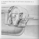
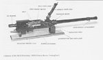
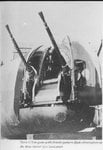
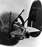
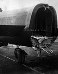
The Nash and Thompson Type FN.20 Tail Turret

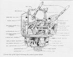
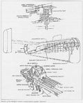
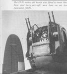
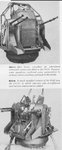
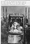
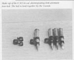
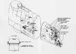
This turret was the most important of the Parnall range, providing rear defence for most of the aircraft of Bomber Command. The designers at Tolworth had been asked to redesign the FN.4, incorporating modifications suggested by Gunnery Leaders on the squadrons. An armoured shield was fitted, and the gunner was provided with a clear-vision panel, but the main improvement was in the ammunition supply. The ammunition boxes in the FN.4 were fitted in the turret under the guns, which limited the supply and affected the trim of the aircraft. A new supply system was devised in which large capacity boxes were fixed to the sides of the rear fuselage, the ammunition belts being taken from the boxes along steel tracks to the base of the turret.

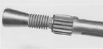
Entering at the base by way of rotating right-angle elbow joints, they were taken through ammunition booster units. These were needed because by the time the belts had reached the guns the weight was far too heavy to be pulled into the breeches by the gun feed mechanisms. The FN servo feed units were an ingenious design in which powered sprockets were automatically energised when the belt pull was more than the gun feeds could handle.

The servo feed unit was driven by a hydraulic motor, two pipes connecting it to the pressure and exhaust lines of the turret feed system. The drive was transferred to the sprockets by four friction clutches. When the guns commenced firing, the belts between the sprockets and the guns tightened, and the platen arms moved across, engaging the clutches. If a belt jammed, an overload device disengaged its clutch. When the obstruction was cleared the clutch could be re-engaged by hand.

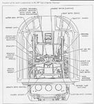
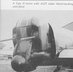
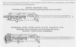
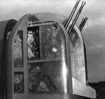
Three 9 mm (0.354 in) armour plates, hinged horizontally and moving in unison with the guns in elevation, afforded protection to the gunner's front. The armour affected the gunner's field of view, and also limited the amount of ammunition that could be carried on some long-distance sorties because of its weight. Some Groups decided that rather than set out on a long trip with less than a full supply of ammunition, a better weight-saving idea was to dispense with the armour.

In common with most turrets, when operating at the very low temperatures encountered on night operations, the gunner's view was often restricted by misting and frost glazing the cupola. It was not uncommon for a gunner to smash the Perspex front panel to give a better field of view. Although this added to his physical discomfort it was thought that the clear view was well worth a few degrees' drop in temperature. The removal of the front panel soon became widespread, leading to an official modification to turrets coming off the line at Yate. The front panel was then mounted in side grooves, allowing it to be dropped to give a clear view to the front.

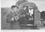
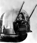
The gunner entered the FN.20 from the fuselage. After clipping his parachute to quick-release hooks just inside the turret, he climbed into his seat and closed the sliding doors behind him, securing the locking catch. On early models of the turret, during violent manoeuvres the catch sometimes gave way, allowing the doors to slide open. Without a backrest the gunner fell back into the fuselage and regained his position only with great difficulty. The catch was redesigned and strengthened.

The turret controls were basically the same as in all Parnall tail turrets, with some modifications.

The triggers on the twin-handled control column operated the four Palmer hydraulically gun-firing valves via Bowden Cables. On some experimental FN.20s used on high-altitude operations, the triggers operated electrical switches controlling relays. The four Browning guns were harmonised to a point 229 m (250 yds) distant on to a 3 m (7ft 6 in) square for night operations, and 366 m (400 yds) on a 2 m (5 ft) square for daylight sorties. The FN.20 turret was popular with gunners, and, apart from the clear-view panel and door catch, few modifications were needed.

All the usual ancillary services were fitted to the turret. Provision was made for observing the angle of drift to assist the navigator, and a more efficient form of oxygen supply was installed. This consisted of an oxygen economiser which regulated the supply to the gunner according to demand. Problems had occurred with the old Type E oxygen masks, and a new mask, Type G, was issued at the time of the introduction of the FN.20. This mask fitted the Type B helmet, and few problems were encountered with the oxygen equipment after this.

The gunner could abandon the aircraft by opening the doors, grabbing and clipping on his parachute, traversing the turret to the beam stops, pulling the pin from his seat harness and falling out backwards. In the event of the gunner being injured, another member of the crew could release the door catch from the fuselage, and there was also a manually operated hydraulic valve outside the turret which enabled the turret to be turned from outside. This facility was added after injured gunners had been trapped inside with fatal consequences. If the hydraulic supply failed, the gunner could turn the turret by disengaging the rotation drive and turning a handle which operated a pinion acting on the gear teeth of the fixed turret ring.

When the Wellington Mk.VI high-altitude bomber was being designed Parnall were asked to provide a pressurised tail turret which was to be known as the Type FN.70, but it was soon found that such a project would need new technology, and the time needed was not available. The Wellington Mk.VI was eventually fitted with a remotely controlled FN.20 turret sighted from a dome in the pressure cabin.

In late 1944 a modified FN.20 was introduced and, as this incorporated new parts, it was designated the Type FN.120. The weight was reduced by 18 kg (40 lb) and some of the main structural members were redesigned. The most popular feature from the gunner's point of view was an improved heating system.

Details of the Type FN.20 Tail Turret

Position in aircraft: Tail
Motive power: Hydraulic motor
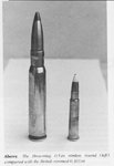
Armament: Four 7.7 mm (0.3030 in) Browning Mk.II guns
Ammunition: 2,500 rounds per gun; 1,900 in fuselage boxes, 600 in feed tracks
Ammunition feed: FN hydraulic servo feed from fuselage boxes
Gunsight: Mk.III free mounted reflector sight; Mk.IIC gyro gunsight
Fire control: Palmer electric
Field of view:
Traverse: 94 degrees to each beam
Elevation: 60 degrees
Depression: 45 degrees
Weight of turret (empty): 148 kg (325 lb)
Weight (operational): 614 kg (1,350 lb) = gunner - 82 kg (180 lb); guns - 40 kg (88 lb); ammo - 218 kg (480 lb); boxes - 15 kg (33 lb); tracking - 23 kg (50 lb)
Diameter of ring: (30 1/2 in)
Armour (when fitted): 9 mm (0.354 in) armoured plates to front aspect
 

Attachments

  • fn.20.jpg
    fn.20.jpg
    33.6 KB · Views: 3,048
  • fn.20___fn.120.jpg
    fn.20___fn.120.jpg
    24.3 KB · Views: 2,243
  • fn.20__a_.jpg
    fn.20__a_.jpg
    44.1 KB · Views: 2,676
In 1933, at the request of the US Army Air Corps, two 7.62 mm (0.300 in) versions of the 12.7 mm (0.50 in )M2 were produced. The first was a pilot's gun, while the second, the M9/402, was designed as a pivoted observer's gun with a higher rate of fire and longer barrel length. Just after these guns had been produced, the RAF decided to hold competitive trials to select a modern automatic gun. The guns tested were the Vickers, Hotchkiss, Darne, Madsen and the Colt MG40 and MG40/2. The winner was the Colt 40/2, which proved the to have the best all round performance.

Once the gun had been selected, the Martlesham Heath gun section under Major Adams conducted Service trials. It was found that the cordite-filled 7.7 mm (0.303 in) cartridges used in Britain caused serious trouble (most countries used nitrocellulose propellent, which was less sensitive to heat than cordite). When a long burst was fired a round remained in the chamber, and the cordite then detonated. Major Adams redesigned the action to hold the breech-block to the rear with the chamber empty. The first trials of production guns from BSA showed a weakness in the feed. This meant a further extensive redesign, until the final gun was quite different from the MG40/2.

The Browning gun was the first in RAF use to have the facility of adjusting the barrel in relation to the breech-block. Some armourers adjusted the barrel too far forward, leaving too much of the case protruding from the barrel, so that the end of the round was blown off causing a 'separated case' stoppage. With experience this problem was overcome, and durng the Battle of Britain, if a fighter returned from a sortie with a separated case stoppage the armourer responsible was put on a charge. Trouble was also caused by excessive fouling of the muzzle attachment, the guns seizing after about 200 rounds. A sharp pen-knife seemed the best way to clear the hard residue. In 1940 BSA redesigned the muzzle attachment by adding cooling fins and chromium-plating the bore of the unit. This modification caused a hold-up to production at a vital period, but the gun could then fire 300 and more rounds without fouling. After the troubles were rectified, production at BSA, Vicker-Armstrongs and sub-contractors kept up with the demands of the Service (one Hurricane and Stirling needed 16 guns).

The Browning was a recoil-operated gun with safety features which ensured near trouble-free operation. The gun was fired when the rear sear was depressed. This was done by hand, or by pneumatic, hydraulic or electrical solenoid actuation, depending on the installation. With sufficient maintenance, malfunctions were minimal. The most usual stoppage was caused by rogue ammuntion or badly made-up belts, though the links would also sometimes jam in the ejection outlet. Turret gunners could clear stoppages with a hooked tool kept handy in the turret, and gunners also kept a looped wire or hooked metal cocking tool to clear the gun. Stoppages were reduced after special belt-making machines were introduced.

Very cold conditions could also lead to problems. Heaters were provided in fighter gun bays, but oil spillage in some power turrets made heaters a safety hazard. Anti-freeze oil helped, and one Bomber Group fixed a paper seal over the cartridge ejection slot to stop the fierce draught which could enter the aperture. The 'fire and safe' unit mounted on the side of the gun body was operated by a pneumatic actuator on the same pressure line as the sear release unit on fighter aircraft. Turret guns were fired by hydraulic units or electrical solenoids controlled by triggers or push buttons on the turret control handle. The guns were made safe by pressing a release pin at the back of the fire and safe unit.

Each gun was marked with its number and Mark designation. Marks 1 and 11 were almost identical, having the early muzzle attachment; Mk11* guns were fitted with the BSA modified unit.

The Browning was rarely used as a free-mounted gun, except in Beaufighter TF Mk.Xs of Coastal Command, where the observer's cupola was so small that the ammunition drums of a Vickers could not be accommodated. Otherwise, when a free-mounted gun was needed, the Vickers K was used.

Browning Gun Production

A total of 460,000 complete Brownings were manufactured in the UK with spares for another 100,000. Most of these were manufactured by BSA but an extensive sub-contract scheme was set up in 1941, BSA supplying key personnel and supervising the work. Series production started in 1938, when 3,809 were produced, and production figures rose until in 1942 16, 300 were completed. Production contracts were competed by the end of 1944, and in 1945 the lines were closed down.

Details of the 7.7 mm (0.303 in) Browning

Calibre: 7.7 mm (0.303 in)
Action: Recoil
Cyclic rate: 1,150 rpm
Weight: 9.9 kg (21 lb 14 oz)
Muzzle velocity: 811 m /sec (2,660 ft/sec)
Ammunition feed: Metal links
Cooling: Air
Rifling: Five grooves, left-hand twist, 1 turn/10 calibres
Length: 1,130 mm (3ft 8 in)
Weight of Bullet (Mk VIII): 11.34 grams (0.4 oz)
Maximum Range: 914 m (3,000 yds)

------

The last photo show the tools used by Air Gunners for clearing blockages and recocking the Browning manually
 
Browning Ammunition Belts

Browning ammuntion belts were made up in the early war years by armourers using hand-wound belt-making machines. On some occasions the bullets were even inserted into the links by hand. The make-up of the belts varied with the unit: in most Bomber Command Groups one in five rounds was tracer, but AP and incendiary rounds were often included, especially in fighter units. When the Plessey electrically powered belt-making machine was introduced, the work of the armourer became a little less irksome. The bullets were fed into a hopper one end, and when the machine was switched on a continuous belt was produced from the other.

Identification of 7.7 mm (0.303 in) ammunition used in the Browning and Vickers K.

Service ammunition is identified in several ways, viz:

1. Labels on the container; 2. A code stamped on the base of the cartridge case; 3. Coloured dye on the annulus of the round (centre of the base); and 4. Colouring of the bullet tip (1939-1945)

The base marking gives the main details. These consist of: A. Code initials of manufacturer; B. Year of manufacture; C. Type of propellent (usually only Z for nitrocellulose); D. Mark of cartridge; and E. Type of bullet. The annulus colour code is found in the centre of the base, and signifies the following: Black: Ball until 1918; Purple: Ball after 1918; Blue: Incendiary: Orange: Explosive, including PSA; Red: Tracer.

During the 1939-45 war, station armourers needed a more instant way of identifying special ammunition. The method adopted was to colour the tips of the bullets, the code being as follows: Blue tip: some marks of incendiary; White tip: air-to-air short-range day tracer; Grey tip: air-to-air short-range night tracer; Black tip: observation bullet; No colour: ball.

Head Stamps

Each manufacturer was given a code to be used on the head stamp on the base of the round. The main makers were: BE - ROF Blackpole (1939-45), CP - Crompton Parkinson, E - Eley, FN - Fabrique Nationale, K - Kynock (ICI) - at various factories (K2, K3, K4 K5), RG - ROF Radway Green, RL and RG - Royal Laboratory Woolich, RW - Rudge Whitworth, SR - ROF Spennymore. Bullet types were also shown on the head stamps, as: AA - PSA or Pomeroy, B - Buckingham explosive, F - semi-armour piercing, G -SPG tracer, K - Brock incendiary, R - Explosive from 1918, T or G - Tracer, W - armour-piercing, Z - Nitrocellulose propellent after 1917. Ball ammunition was stamped VII with no letter.

------

Note the size between .303 and .50
 

Attachments

  • 7.7_mm_browning_ammo.jpg
    7.7_mm_browning_ammo.jpg
    31 KB · Views: 1,940
  • 12.7_mm_browning_rimless___7.7_mm_browning_rimmed_rounds.jpg
    12.7_mm_browning_rimless___7.7_mm_browning_rimmed_rounds.jpg
    18.7 KB · Views: 1,773
12.7 mm (0.50 in) Browning

As the war progressed, the RAF received many US warplanes, and the 'fifty caliber' Browning's fire power was appreciated by British aircrews.

Various UK manufacturers produced turrets armed with the gun in the last years of the war. The Spitfire F.Mk.IXE was also equipped with these weapons, and other British fighters were fitted with them experimentally.

Action

The gun can initially be charged manually or, in turret guns, by hydraulic or pneumatic units. Turret guns are fired by relay-controlled solenoids, free guns by twin triggers at the rear in an E II cradle unit.

When the gun is fired, recoil carries the barrel, barrel extension and bolt backwards a short distance. This unlocks the bolt from the barrel extension and the bolt is thrown further to the rear against the main spring. The empty case is withdrawn by the bolt and the next round extracted from the belt. As the bolt travels forward, the case is ejected and the next round moves into the breech. The rearward motion of the barrel and extension is checked by the oil buffer and spring, which then drives them forward again. This locks the bolt to the firing pin to fire the new round. This cycle continues as long as the sear is depressed and
ammunition is available.

The rimless ammunition is unusual in that there is no copper driving band normally found on such weapons: in consequence, the armour-piercing rounds caused heavy barrel wear.

12.7 mm Browning Cartridge Identification

Ball: Gilded metal (copper-coloured)
Armour-Piercing: Black tip
Tracer: Red tip
Incendiary: Light blue tip
Dummy: Hole in case

Details of 12.7 mm (0.50 in) Browning

Calibre: 12.7 mm (0.50 in)
Action: Recoil
Cyclic rate:
(M2): 750/850 rpm
(M3): 1,200 rpm
Weight: 29 kg (64 lb)
Muzzle velocity: 838 m/sec (2,750 ft/sec)
Cooling: Air
Rifling: Eight grooves, right hand
Length: 1.42 m (4ft 8 in)
Weight of Bullet: 39.69 grams (1.4 oz)
Maximum Range: 6,583 m (7,200 yds)
 
Sorry bout that.
 

Attachments

  • air_gunner_s_tools.jpg
    air_gunner_s_tools.jpg
    26.8 KB · Views: 1,730
  • 7.7_mm_colt-browning_e.jpg
    7.7_mm_colt-browning_e.jpg
    24 KB · Views: 2,333
  • 7.7_mm_colt-browning_d.jpg
    7.7_mm_colt-browning_d.jpg
    45.2 KB · Views: 1,939
  • 7.7_mm_colt-browning_a.jpg
    7.7_mm_colt-browning_a.jpg
    47.5 KB · Views: 2,089
  • 7.7_mm_colt-browining_c.jpg
    7.7_mm_colt-browining_c.jpg
    18.8 KB · Views: 1,583
First some background on AVM Rice. From RAF.mod.uk

Air Vice-Marshal Sir Edward Rice KBE, CB, CBE, MC

AOC 1 Group 1942-5

A chance meeting between Edward Rice and the head of the engineering firm Rose Brothers led to the design of the successful Rose-Rice twin 0.50in Browning tail turret for Lancasters of 1 Group. Despite a lack of any official interest, Rice went ahead and helped Alfred Rose with the winning design and the Air Ministry placed an initial production order for the turret in June 1943.

The son of a Berkshire doctor, Edward Rice was born on 19 December 1893 and educated privately before transferring to the RFC from the Army in 1915. After a succession of overseas postings during the 1920s and '30s, he was promoted to Air Commodore in 1940 and appointed AOC RAF West Africa from 1941 to 1942. Returning to England in 1942, Rice was promoted to Air Vice-Marshal to command 1 Group until February 1945 when he was appointed AOC 7 (Training} Group, where he remained until his retirement from the service in 1946. He died soon afterwards on 14 April 1948, aged fifty-four


And a Pic of the turret itself from the intital source. further details to follow.
 

Attachments

  • avmrice.jpg
    avmrice.jpg
    7.7 KB · Views: 1,613
  • twin_turret_mounted_12.7_mm_colt-browning_m2.jpg
    twin_turret_mounted_12.7_mm_colt-browning_m2.jpg
    26.6 KB · Views: 2,101
If anyone has any data about the 0.5 cal turret similiar to the 303 data... I'd appreciate it..

Kiwi... this stuff is great...

Simon
 
I will get the data on a few turrets including some specials later.

Here is comparison images between the two and a Gunner with big hairy ones demonstrating the correct method to leave the building. :shock:
 

Attachments

  • 303comp.jpg
    303comp.jpg
    18.4 KB · Views: 2,095
  • size50.jpg
    size50.jpg
    27.7 KB · Views: 2,048
  • bail1.jpg
    bail1.jpg
    21.5 KB · Views: 1,843
  • bail2.jpg
    bail2.jpg
    20.4 KB · Views: 1,759
Mid Upper Cannon equipped turret.

Here is the info from the original source, with a couple of schematics.

Then I thought, "hang on I have a pici lurming somewhere". a test for airworthness? a rare sight anyway.

And a .50 mid upper for comparison.

------

The Boulton Paul Type H Mid-upper Turret

The Type H turret Mk.II was a development of an early design project started in May 1939, to arm the Halifax and Stirling, with a twin-cannon armed dorsal turret, the BP Type H Mk.I, together with a proposed twin-cannon under defence turret, the BP Type O. These being cancelled before any metal was cut. The Later Mk.II project was ordered in February 1942 as an mid-upper turret for the Lancaster. It was to be armed by twin 20 mm (0.78 in) Hispanos or two 15 mm (0.59 in) cannon of a type developed by Vickers at Crayford*. The Vickers guns did not materialise, however, and the first prototype was a test-firing mock-up with 20 mm (0.78 in) Hispano guns. By September 1942 the company was ordered to give the project top priority, and five prototypes were requested by the Air Ministry on 14 September. By 23 September this number had been increased to six, together with a Lancaster mock-up.

By January 1943 the signs were that the Lancaster would soon be armed with a Type H mid-upper turret. The production drawings were 55 per cent compete, two prototypes were nearly finished and ground firing was scheduled for April. On 27 February a directive was received from the Air Ministry cancelling further development: the project was to be abandoned so that the company could concentrate on 12.7 mm (0.5 in) Type Ds, and an 'ideal' Lancaster front turret, the Type F, together with a remotely controlled barbette defensive system. Such were the frustrations of wartime design and production.

The main structure of the Type H turret comprised an upper section and skirt above the turret ring and a lower section below the ring. The upper part of the turret was divided into three: a central compartment, into which the gunner's head and shoulders projected, which had a central Perspex sighting panel to the front, and a gun compartment to each side. This arrangement protected the gunner from the considerable fumes given off when the Hispanos were fired. The empty cartridges and links were collected in boxes under the guns, after being deflected by side plates at the sides of the turret.

As can be seen in the illustration, the gunner sat well forward in the turret, his feet supported by an extension platform fixed to the turret base. He entered the turret from the front, by swinging the control table out horizontally. The turret had provision for emergency hand operation in rotation only, a feature which was meant for emergency escape. Gun elevation and firing could not be carried out with the power off. The Mk.IC gyro sight was mounted on a sight bar, connected by a parallel linkage system to the turret elevation control. The gunner was provided with a socket for heated clothing, the standard interphone jack, and a regulated oxygen supply. The turret was heavy, with guns and ammuntion it weighed 2,425 kg (1,100 lb). This would have been quite a penalty had it been accepted for use. The gunner was protected by an armoured apron extending round the front of the turret, the 12 mm (0.48 in) plates protecting all except his head. The electro-hydraulic power unit was mounted behind the gunner, giving a maximum rotation speed of 35 degrees/sec; a minimum speed of 0.25 degrees/sec could be achieved when adjusting aim. The guns were limited in traverse to 45 degrees either side of aft, with elevation limits of 50 degrees up and 9 degrees below horizontal.

Details of the Type H Mk.II Turret

Power system: Modified BP electro-hydraulic
Armament: Two 20 mm (0.78 in) Hispano Mk.II cannon
Ammunition: 300 rounds per gun
Ammuntion feed assisters: Drive sprockets for the two guns driven through separate electromagnetic clutches from a common electric motor. Clutches activated by belt tension.
Operating limits:
Traverse: 45 degrees
Elevation: 50 degrees
Depression: 9 degrees
Power requirements:
Voltage: 24 v
Current: Normal 50 amps; high speed 75 amps
Turrets speeds: Max: 35 degrees/sec; Min: Less than 0.25 degrees/sec
Gunfire interrupter: Electro-mechnical type proviidng separate control for each gun
Turret weight: Empty: 227 kg (500 lb); Armed: 449 kg (1,100 lb)
Gunsighting: GGS Mk.IC (proposed)
Turret dome: Not detachable, consisting of Perspex and metal panels mounted on frame members. The sighting panel could be powered to slide upwards leaving a clear space for night sighting
Turret sizes:
Overall height: 176 cm (69.25 in)
Dome diameter: 112 cm (44 in)
Dome to skin line: 65 cm (25.25 in)
Fuselage opening: 94 cm (36.75 in)

The Boulton Paul Type H Mk.I Turret

Aircraft type: Handley Page Halifax, Short Stirling
Type Mark: H.Mk.I
Position: Mid-upper
Guns: 2 x 20 mm (0.78 in) Hispano Mk.II
Traverse:
Elevation:
Depression:
Status: Cancelled before production

The Boulton Paul Type O Mk.I Turret

Aircraft type: Handley Page Halifax, Short Stirling
Type Mark: O Mk.I
Position: Mid-under
Guns: 2 x 20 mm (0.78 in) Hispano Mk.II
Traverse: 90 degrees
Elevation: 0 degrees
Depression: 70 degrees
Status: Cancelled before production

The following aircraft were fitted with the Boulton Paul Type H Mk. II
Turret

Aircraft: Avro Lancaster (Not allocated)
Type Mark: H Mk.II
Position: Mid-upper
Guns: 2 x 20 mm Hispano Mk.II
Traverse: 90 degrees
Elevation: 50 degrees
Depression: 90
Status: Experimental
 

Attachments

  • bpcannon.jpg
    bpcannon.jpg
    17.9 KB · Views: 2,083
  • bp_type_h_turret2.jpg
    bp_type_h_turret2.jpg
    29.5 KB · Views: 1,640
  • bp_type_h_turret.jpg
    bp_type_h_turret.jpg
    29.5 KB · Views: 1,940
  • 50upper.jpg
    50upper.jpg
    24.2 KB · Views: 1,557
The Lancaster twin Cannon Barbette Defence System (1944)

In early 1942 the company received a development contract for a completely new defence system for the Avro Lancaster. It was decided to switch some Lancaster squadrons to daylight operations, and the new project was to consist of dorsal and ventral turrets controlled by a gunner in a sighting cockpit in the tail. Each turret, or barbette as they were officially called, was fitted with two 20 mm (0.78 in) Hispano guns, supplied with 200 rounds of ammunition. The control system was all-electric, the turret mechanisms being linked with a specially designed sighting system which compensated for range and deflection. It was then decided to install AGLT radar-assisted gunlaying, and this was incorporated into the gunner's control system, giving blind tracking facility.

The prototype barbettes were completed and despatched to RAE Farnborough in early 1944, where they were fitted to Lancaster (LL780G). Some trials took place, but it was thought that hostilities would probably be ended by the time the system was ready for operational use, and the project was terminated in autumn 1944.

Second pic is Lancaster (LL780G) fitted with the mid upper + lower barbettes during trials of the system 1944.
 

Attachments

  • lancaster_fitted_with_upper___lower_barbettes.jpg
    lancaster_fitted_with_upper___lower_barbettes.jpg
    24.5 KB · Views: 1,711
  • upper___lower_barbettes.jpg
    upper___lower_barbettes.jpg
    24.5 KB · Views: 3,173
sorry here it is
 

Attachments

  • layout_of_the_bp_remotely_controlled_defence_system.jpg
    layout_of_the_bp_remotely_controlled_defence_system.jpg
    46.3 KB · Views: 2,395
This is the clearest picture I have found. It is of the Boulton Paul turret simmilar to the F.N. in its construction.

Also the perils of night bombing. What happens when the plane above hits your turret with a 500 pound bomb.
 

Attachments

  • type_k_under_defence_turret.jpg
    type_k_under_defence_turret.jpg
    23.1 KB · Views: 1,696
  • oops.jpg
    oops.jpg
    20.8 KB · Views: 1,616
here is two pics. 1 is the lanc with F.N. turret.

The next is a Halibag with the Presto-Green .50cal ventral turret. This unit was predominantely used by Canadian Halifax crews.

Out of interest the F.N. turrets were manufactured by a company called Nash Thompson, a subsidary of Parnall
 

Attachments

  • prestongreen ventral.jpg
    prestongreen ventral.jpg
    27.6 KB · Views: 3,524
  • ventralfnturret.jpg
    ventralfnturret.jpg
    44.4 KB · Views: 2,008
Excellent posts guys, I would have loved to have seen the twin cannon barbette system married up to the Rolls Royce Nene engine variant. It would have been awesome. :)
 
From the original source.

The Boulton Paul Type D Tail Turret
After four years of indecision the Air Staff finally issued production orders for turrets armed with heavy-calibre guns. Both Parnall and Boulton Paul had previously submitted designs for such turrets, but circumstances had prevented their adoption. Boulton Paul designers decided to embark on a completely new design which proved to be extremely roomy and efficient. The new turret was armed with 12.7 mm (0.5 in) Browning guns mounted low and to each side of the seated gunner. The turret had a fabricated structure, most of which was above mounting ring level, the guns being mounted upright in cradles. The ammunition supply was located in the centre fuselage well forward of the turret, thus placing the heavy boxes 255 kg (560 lb) when loaded near the centre of gravity. The structure of the turret consisted of two outboard members carrying the outer bearings of the gun cradle, and two inner sections supporting the inner bearings. The gun mountings were quite substantial, being strengthened Type T turret mountings. The turret was designed for the Mk.IC gyro sight, but this was replaced by the improved Mk.IIC gyro. The sight was mounted on a horizontal tube supported by two levers which were connected to the torque tube to move in harmony with the gun cradles.

The power system was the usual electro-hydraulic unit, with one modification - the elevation mechanism was changed from a hydraulic ram to a hydraulic motor, which was found to be more accurate in control at slow speeds. The gunner sat at his control table with the well-proven controllers to his front, while his central sighting panel was supported in channels which permitted it to slide downwards, leaving an open aperture when conditions were such that sighting through the panel was difficult. Two side panels were also arranged to slide open if needed. The turret doors were mounted on tracks, the two doors meeting in the centre and locking automatically when the outer edges were pushed outwards. There was provision for hand turning the turret in the event of power failure. The 'Free' and 'Engaged' lever was set to the 'Free' position, which automatically broke the gun-firing circuit and disengaged the drive. If the gunner was incapacitated, the turret could be turned by pressing a switch in the fuselage outside the turret, which enabled the dome to be turned until the doors could be opened and the gunner taken out.

The heavy ammuntion belts were stored in boxes in the rear fuselage, and the feed mechanism worked as follows: when the firing button was pressed, an electrical relay was energised which switched on powered sprockets which pulled the belts out of the boxes, feeding them through ducting to the 90 degrees bends at the turret base. Ammunition feed assisters then hoisted the belts into the guns, which were controlled by clutches which engaged when the belts reached a preset tension, ensuring an even feed. The guns were fired by Dunlop Maxifort solenoids, and cocked by hand lever chargers of BP design. The gun barrels were aligned with the sight by lock nuts on the rear support mounting, the guns being usually set to converge at 549 m (600 yds). The electrical load of the turret was considerable, a load of 130 amps was needed, and the maximum load of the main drive motor was 330 amps during the start sequence, though the average was 45 amps. Gun heater, feed assisters, and firing solenoids all needed considerable power, and after problems with the circuit breakers on full load, arrangements were made to cut off the gun and the AGLT scanner heaters (see below), when the guns were fired. An accumulator charged by the aircraft generator supplied the 24 volt power, all fuses and circuit breakers being in easy reach of the seated gunner.

As mentioned above, the guns were sighted by the Mk.IIC gyro sight, the range control of the sight being operated by the gunner's right foot. The selector dimmer and height and airspeed control boxes were fixed on the right hand gun chassis support tube. The sight switch and fire/safe switches were fitted to the top right of the control table. If a Mk.IIIA reflector sight was used, the graticule illumination was controlled by the rheostat on the sight. The Type D was the first to be fitted with the AGLT (airborne gun-laying turret) blind tracking radar system, codenamed Village Inn. The control panel for this was behind the gunner's right shoulder, the spot cut-off switch being fitted on the control table. A system of IFF (identification friend or foe) was devised, using an infra-red detector which would identify any friendly aircraft approaching from the rear fitted with an infra red lamp in the nose. The receiver, which used a 10,000 volt detector, was fitted to a bracket mounted to the left of the gunsight, the control box for the system being mounted between the gunner's legs. Gunners were not altogether happy with the mechanism, as they could imagine themselves being electrocuted in the event of battle damage or a loose connection.

The prototype turrets were manufactured at the company's Pendeford Lane works, where most of the development took place. The main production was undertaken by Joseph Lucas, where most Boulton Paul turrets were made. The first squadron aircraft to be fitted with the new turret was the Handley Page Halifax VII, which used the Type D in operations in the last months of the war. The turret was the contemporary of the Parnall FN.82 which was designed for the same specification, but after its successful use in the Halifax it was the Type D which was chosen for the Avro Lincoln heavy bomber, which served for many years after the war.

Several Type D turrets still exist, many having been rebuilt by enthusiasts. A prime example can be seen at the Royal Air Force Museum at Hendon, where it is exhibited on a stand.

Details of the Type D Turret

Position: Tail
Motive power: BP electro-hydraulic
Power source: Accumolators charged by aircraft generator
Operating voltage: 24 v
Armament: Two 12.7 mm (0.5 in) Browning No.2 Mk.II guns
Ammunition: 1,515 rounds per gun
Belt feed assisters: BP booster units, Dunmore motors
Firing system: Dunlop Magnovox solenoids Type 14 D.I:G:S
Gun chargers: Hand levers, BP design
Armoured shielding: 9 mm (0.354 in) plate. front aspect
Gunsighting: GGS Mk.IIC gyro sight, or Mk.IIIA reflector sight. Light models AGLT Blind Tracking Radar
Weight of turret:
Empty: 200 kg (440 lb)
Armed: 249 kg (548 lb)
Weight of guns: 33 kg (72 1/2 lb)
Weight of ammunition: 415 kg (914 lb)
Operating limits:
Traverse: 90 degrees either side
Elevation: 45 degrees above horizontal
Depression: 45 degrees below horizontal
Speed of operation:
Traverse: 35 degrees/sec
Elevation: 35 degrees/sec

The following aircraft were fitted with the Boulton Paul Type D Turret

Aircraft type: Handley Page Halifax B.Mk.VII; Avro Lincoln B.Mk.I II
Type Mark: D.Mk.II
Position: Tail
Guns: 2 x 12.7 mm (0.5 in) Browning No.2 Mk.II
Traverse: 180 degrees
Elevation: 45 degrees
Depression: 45 degrees
Status: Series production
 

Attachments

  • bp_type_d_turret.jpg
    bp_type_d_turret.jpg
    39.9 KB · Views: 1,884
  • diagram_showing_type_d_control_details.jpg
    diagram_showing_type_d_control_details.jpg
    65.1 KB · Views: 2,220
  • main_components_of_type_d_turret.jpg
    main_components_of_type_d_turret.jpg
    56.3 KB · Views: 1,577
  • remote_ammo_system.jpg
    remote_ammo_system.jpg
    41.2 KB · Views: 1,498
  • type_d_turret_with_aglt.jpg
    type_d_turret_with_aglt.jpg
    35.5 KB · Views: 2,139
Dear members
This may have been answered before. Is there anyone who can tell me where I might find turret manuals
Regards

Des Brinn
 
I think its also worth mentioning that the AGLT Blind tracking Radar was very accurate. So much so that British bombers were fitted with a sensor to show up on the gunners sight.
There was more than one case of the Gunner firing at and hitting other allied aircraft that had strayed into the arc of fire. Officially the bombers never actually fired but did track targets but then again, no one ever explained how some damaged Halifax's and Lancasters were hit by .50 bullets either.
 

Users who are viewing this thread

Back