Avro Lancaster Dambuster - CG Model

Ad: This forum contains affiliate links to products on Amazon and eBay. More information in Terms and rules

peter_f

Recruit
6
0
Jan 16, 2010
Hello Everyone,
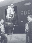
I'm new here and I would like to show You my new work in progress and ask You for help. After finished Avro Lancaster Mk III I decided to create its dambuster version for new series of images. Unfortunatelly the quality of many photos of Dambuster Lancaster is too poor to be used as detail reference for the model. When I was modyfing my old model relying on documentary photos and drawings as well as on photos of plastic models. But for higher quality more details are needed. Maybe there is some better quality reference photos or drawings. Can You help, please?

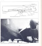
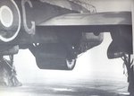
Here are shots of my Dambusters modification and below my old Lancaster model

30669016.jpg


17858181.jpg


13160097.jpg


56149154.jpg


And render with pointed missing details and parts (Orange - parts with missing details, RED - missing parts

57712142.jpg


62555537.jpg


86025768.jpg


62037515.jpg


14008495.jpg

26168642.jpg

58685591.jpg

35249037.jpg

89511464.jpg


frontmag.jpg

rightmag.jpg

bottommag.jpg

leftmag.jpg

topmag.jpg
 
Thank You very much for Your kind words guys :)
I wish my dambuster had similar level of detail as my old Lanc. But where to find good documentation? Do You know?

Below some more shots of details:

61823040.jpg

20062527.jpg

82951938.jpg

31651138.jpg

64998452.jpg

43181925.jpg

lancastrbeauty.jpg

fn50front.jpg

fn50left.jpg

fn50back.jpg

fn50p.jpg

perspective1.jpg

perspective2.jpg

rightr.jpg

frontsy.jpg

leftyg.jpg

animationni.gif
 
Nice work ! There's not a lot of detail needed really, as the Lancs were standard aircraft, modified for the operation. There wasn't any extra externall detail, AFAIK, that isn't already present on your 'model', with the possible exception of the ventral guns, which were deleted on all but one aircraft which took part in the raid. And, of course, the spot lights.
I notice the bomb sight mount appears to have a vertical bar each side which didn't exist. This may have been confused with the turret ammunition tanks.
 
Thank You so much Wayne, B-17engineer and Airframes !

Airframes: Many many thanks for Your help! Saying about details I meant some additional cables attached to construction, screws etc. What was AFAIK? Which Lancaster had FN50 turret not deleted?
Please find below image with questions. Do You think it is possible to settle the answers on these questions? Thank You so much!

questionsz.jpg
 
GREEN: This was a 'solid' fairing, and did not open.
RED: Spotlight opposite side. The opening here was for the standard strike camera, not of use on the raid.
BLUE: No extra cables etc. The drive belt was on the Starboard side.
ORANGE: This area was more flat, with a slight curve, not as rounded as your projection.
MAGENTA: Second spotlight in the orange fairing.
CYAN. This was the standard lower fuselage. The ventral guns, when fitted, where in this section.
I'd need to check which aircraft on the raid had the ventral turret. The aircraft was a last minute replacement, I think for McCarthy. I might be able to find you photographs of the detail areas mentioned, and a AVRO drawing of the 'Upkeep' installation, but it'll take a few days, as I'm behind with a lot of stuff at the moment.
 
Thank You very much B-17engineer and Airframes!
Airframes: I just don't know how to thank You for Your help! This would be great If You found some reference photos! I am VERY appreciate for Your help!!!
 
peter_f

Above all praise!
A remarkable and very high-quality work!
 
Here are the photos and drawings. Most are in the public domain, but the detail drawings of the Upkeep installation and the arming of the mine are from 'The Dam Busters Story', by Jonathan Falconer (the ones on PDF).
It's not clear, but the front spotlight was on the starboard side of the nose (left as viewed) near the antenna. The rear spotlight was in the starboard, rear, of the rear bomb bay fairing. Note the shape of this. The photo of Gibson entering 'G' is to show the position and size of the static vent. This is the rounded-end rectangle, to the right of the door, beneath the letter 'E' of the serial number. This was a bare metal plate.
If you need clear photos of the framework in the bomb aimers position let me know. In your 'model', the shape and structure is incorrect.
Hope this helps.
Terry.
 

Attachments

  • Can Jan 350.jpg
    Can Jan 350.jpg
    50.6 KB · Views: 484
  • Can Jan 351.jpg
    Can Jan 351.jpg
    94.1 KB · Views: 323
  • Can Jan 352.jpg
    Can Jan 352.jpg
    60.2 KB · Views: 325
  • Dams diag 1.pdf
    604.6 KB · Views: 205
  • Dams diag 2.pdf
    407.6 KB · Views: 183
  • Dams diag 3.pdf
    529.4 KB · Views: 177
Absolutely amazing work!!!!
I don't know how i missed this thread previously???

I've only just last night finished reading this book....

21563.jpg
 
Thank You so much Epizikl, Lancaster630, Airframes and Peebs for Your so kind words and great help.
Thank You Terry for such clear photos and diagrams. Will be very helpful!!
 

Users who are viewing this thread

Back