Supercharged
Airman
Hello,
by the way, this is my first post in this forum. I'am watching and reading here as a guest frequently for at least 10 years, so i decided to join because a lot of guys are aviation experts in here.
And now my question, it is about the design of the elevator(flight control surface) of the Boeing B-29 and its successors(B-50) which used the same design. As most of you might already know, aircraft of this size and weight need static and aerodynamic balanced flight controls, otherwise it would be impossible for the pilot to get the surfaces in the desired postion(at higher speeds). In case of the B-29 you have static(weight) balanced elevators both sides interconnected via a torque tube. At this torque tube you have two connections to the flight control cables running forward for captain and f/o side.
That's it
There is no servo tab, springloaded tab or flettner tab....nothing that would reduce the aerodynamic loads for the pilot. Except two trim tabs(one on each elevator) but this tabs have no connection to the torque tube(input) or to the horinzontal stabilizer aft spar. It is written in all manuals that this trim tabs are for elevator trim only.
I used several resources for my search:
-AAF 50-9 The B-29 - Airplane Commander Training Manual for the Superfortress Rev.1 Feb. 1945
-AAF 51-126-6 B-29 Pilot's and flight engineers training manual for the superfortress
-AN 01-20EJ-1 Pilot's Flight Operating Instructions for B-29 and B-29A Airplanes Rev.10 Feb. 1945
-T.O. 01-20EJ-2 Erection and Maintenance Instructions for Army Model B-29 Airplane Rev.20 Aug.1944
- Red Star Vol. 7 Tupolev Tu-4 (Yefim Gordon)
How is it possible for a B-29 Pilot to move the elevator at higher speeds?
Many thanks in advance
Pictures below:
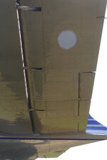
- for reference a KC-97 elevator, same design as B-29 you can see the trim(only) tab
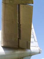
- a DC-6 elevator, just an example for an aircraft of comparable size to the B-29, you can see trim tabs and springloaded tabs
by the way, this is my first post in this forum. I'am watching and reading here as a guest frequently for at least 10 years, so i decided to join because a lot of guys are aviation experts in here.
And now my question, it is about the design of the elevator(flight control surface) of the Boeing B-29 and its successors(B-50) which used the same design. As most of you might already know, aircraft of this size and weight need static and aerodynamic balanced flight controls, otherwise it would be impossible for the pilot to get the surfaces in the desired postion(at higher speeds). In case of the B-29 you have static(weight) balanced elevators both sides interconnected via a torque tube. At this torque tube you have two connections to the flight control cables running forward for captain and f/o side.
That's it
There is no servo tab, springloaded tab or flettner tab....nothing that would reduce the aerodynamic loads for the pilot. Except two trim tabs(one on each elevator) but this tabs have no connection to the torque tube(input) or to the horinzontal stabilizer aft spar. It is written in all manuals that this trim tabs are for elevator trim only.
I used several resources for my search:
-AAF 50-9 The B-29 - Airplane Commander Training Manual for the Superfortress Rev.1 Feb. 1945
-AAF 51-126-6 B-29 Pilot's and flight engineers training manual for the superfortress
-AN 01-20EJ-1 Pilot's Flight Operating Instructions for B-29 and B-29A Airplanes Rev.10 Feb. 1945
-T.O. 01-20EJ-2 Erection and Maintenance Instructions for Army Model B-29 Airplane Rev.20 Aug.1944
- Red Star Vol. 7 Tupolev Tu-4 (Yefim Gordon)
How is it possible for a B-29 Pilot to move the elevator at higher speeds?
Many thanks in advance
Pictures below:
- for reference a KC-97 elevator, same design as B-29 you can see the trim(only) tab
- a DC-6 elevator, just an example for an aircraft of comparable size to the B-29, you can see trim tabs and springloaded tabs