MilSpecArt
Recruit
- 4
- Jan 24, 2022
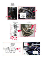
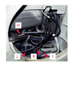
I am restarting work on a fairly serious Fw-190D-9 build in 1/32 scale begun years ago but set aside because of my lack of information on the Jumo 213A-1 engine. The wheel wells are open on the D-9 which means the rear of the engine can be seen, especially the hoses and various lines that carry coolant, fuel, and oil. If you study the images that I have created you will see a number of hoses that proceed from the firewall and connect to the engine. Does anyone know exactly which hoses from the engine ( listed with letters ) connect to the attachment points ( listed with numbers ) on the firewall? There are no diagrams available that show the hoses leading from the rear of the engine to the firewall in the correct order. And photos from various sources show the hoses, but fail to show the necessary transitional views. Who wants to play "Pin the Hose on the Jumo?"
")