Here are the 1/48 scale Light Weight Mustangs that I have spent the last few months on. In the foreground is FR409, the RAF XP-51F, then a XP-51J, two examples of the first XP-51G, then the RAF FR410 XP-51G. Note that both XP-51Gs ended up with the early P-51H (short) tail and the 4-bladed prop. The XP-51Js both presumably had the P-51H tail although I have no information about the second XP-51J. These models were built from the 1/48 Modelsvit P-51H, my second generation canopy, and a lot of milliput. I added the fuselage section below the windscreen to my latest canopy vacuform and that made things much, much easier this time! If I did it again, I might try attaching a P-51D upper to a P-51H lower, but in 1/48 scale it might prove to be a real hassle to match them up.
Navigation
Install the app
How to install the app on iOS
Follow along with the video below to see how to install our site as a web app on your home screen.
Note: This feature may not be available in some browsers.
More options
You are using an out of date browser. It may not display this or other websites correctly.
You should upgrade or use an alternative browser.
You should upgrade or use an alternative browser.
XP-51F/G vs P-51H length.
- Thread starter BarnOwlLover
- Start date
Ad: This forum contains affiliate links to products on Amazon and eBay. More information in Terms and rules
More options
Who Replied?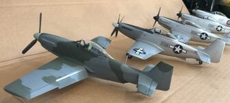
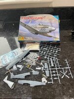
Thanks very much Eric. I think we're very much on the same wavelength - see pile of bits below. The pics you sent are very helpful. The RS Models kit needs a lot of work to get it looking like a good H but it can be done: P-51H "Louisiana Heatwave" in 1/72

 imodeler.com
But not something you want to do too often if you want to keep your sanity. That said, if I want to do F, G and J arm going to have to grit my teeth and get in with it...
imodeler.com
But not something you want to do too often if you want to keep your sanity. That said, if I want to do F, G and J arm going to have to grit my teeth and get in with it...
Nice 1/48 models by the way!
Justin
P-51H Mustang, 1/72 - P-51 - iModeler
By Justin Bedford - This my P-51H in 1/72 scale, built from the RS Models kit. The kit was quite heavily modified to correct some shape issues, and I used the undercarriage and some of the photo-etch from the CMR kit. The model represents the aircraft flown in around 1947 by World War II ace...
imodeler.com
Nice 1/48 models by the way!
Justin
Attachments
drgondog
Major
I feel for guys trying to kit bash XP-51F with a desire for accuracy. For starters, using same scale 'lower' P-51H ), say split at thrust line for reference.
Laying a same scale P-51D upper at the thrust line has the following issues:
1. The lower (P-51H) section aft of the wing needs to remove 13" plug to move the empennage forward. That of course makes the lower cowl line awkward.
2. The wing (of P-51H) has to move fwd about 6"
3. The relationship between the thrust line to top of canopy has to raise about 2-3" - perhaps requiring a long, skinny triangular shim tapering to cowl and also tapering to empenage/fuselge attach point.
The relationship between J and H are significant, but save for cowl section aft of spinner to remove carb scoop (from H to J), the differences in overall dimensions are far less discernable at 1/48 scale.
The 1/72 P-51H looks very nice! I didn't find many errors in the RS Models P-51H kit, so I'm curious what problems you ran into. Certainly the vertical tail is tilted back and needs to be made more vertical. The model looks a lot better with the canopy open as your pictures show. When I close my canopy, it just doesn't look right. I think this is because they did not model the bulging of the bubble canopy. I tried taking one of my F-82 Squadron/Falcon vacuform canopies and fitting it to the P-51H and that immediately looks much better!
I guess we're getting a little off topic, so I'll stop there.
drgondog, do you have a picture or drawing that shows what you are describing? I think that would make the point better than a worded description (1000x, right?)
I guess we're getting a little off topic, so I'll stop there.
drgondog, do you have a picture or drawing that shows what you are describing? I think that would make the point better than a worded description (1000x, right?)
drgondog
Major
I'll scan a P-51H three view showing the reference FS of the wing 1/4 chord location
That would be greatI'll scan a P-51H three view showing the reference FS of the wing 1/4 chord location
T TbirdsRGo , could you tell me where I can find that sectional drawing of the G that you're using please? I've got one similar for the J, but the nose is different of course. Looking closely at the photos you've posted, it seems that the engine bearers are slightly different between the F/G and the H, most probably given the changed location, and I think the depth, of the firewall. If that hunch is correct, that would mean a little bit of rescribing of the RS fuselage engine panels I think.
Justin
Justin, I finally got hold of the XP-51G inboard profile, as some call it. The drawing itself is labeled "general arrangement", so I would go with that.
I used GIMP 2.0 to overlay the XP-51G and XP-51J drawings and the result was pretty much what I expected. They are basically the same from firewall to tailwheel, other than the differences in the engine induction and cockpit heating, which are mostly invisible on the outside. The F had a shorter ventral intake and exhaust, but other than that was very similar to the G.
It's really hard to explain how to get from a P-51D to a P-51H, but it is a lot easier to understand when you go from a P-51D to a XP-51F first, then evolve it into a G and then evolve that into an H. I am basing all of these comparisons on anchoring the wing main spar and letting everything else float relative to that. NAA used several different coordinate frames with the Mustangs, which makes it really confusing to compare locations in inches. Sometimes the origin was at the spinner tip, sometimes it was further back. I think it is easier to just reference everything to the wing, which is what makes it an airplane in the first place.
BTW, I need to walk back a few of my comments from before, such as the differences in P-51D and XP-51F vertical tails...
I suppose it makes sense to go chronologically, so here's the comparison of the P-51D and XP-51G. I'm skipping the F model because I don't have a reliable drawing for it and it's pretty easy to point out the difference between the F and G models.
What you can see here is:
1. The upper profile of the D and F/G were nearly the same (other than the canopy)
2. The lower cowling lines were nearly the same (except that the F/G carb intakes were set a little further back and were not vertical)
3. The entire ventral duct was more streamlined for the F/G (not shown is that the F intake started at about the same location as the D)
4. The leading edge of the vertical stabilizer was more upright on the F/G
5. The F/G had the big canopy, of course.
6. The pilot seat was higher in the F/G but pretty much the same location fore/aft
Not shown is that the whole tailwheel assembly was moved further aft for the F/G, but that is obvious in photos.
It's not really visible in this comparison, but the vertical fin tip was more rounded on the F/G.
Also not seen in this comparison is that not all P-51D aircraft had dorsal fins and the F/G models either didn't have them or they were smaller.
The early P-51s used the wing upper surface for the cockpit floor. The P-51D had a plywood floor added on top of that, but the floor was still so close to the wing that the wing tank fuel gauges could still be viewed by the pilot. Starting with the XP-51F, the floor was raised something like 7" (anybody have an accurate figure?) and there was some rather interesting equipment below the floor. This is not easily visible in the comparsion shown here.
Attachments
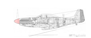
Here's the XP-51G general arrangement drawing by itself.
Key features to note are:
1. raised cockpit floor with the gas-fired Janitrol heater below the pilot's seat. Right above the main fuel tank. No wonder pilots were concerned about this!
2. the pilot seat was hydraulically raised/lowered (vertical the red bar). The horizontal green bar represents the follower links. As the seat was raised, it naturally pushed back a bit.
3. the curved shape of the vertical fin tip is easier to see in this drawing.
4. the upper longeron is horizontal in front, but behind the pilot it is diagonal (by the amount the floor was raised, it appears)
Attachments
I forgot to mention that the firewall of the early Mustangs (NA-73X thru P-51D/K) was more angled than the later Mustangs (F/G/J/H), which were more upright.
The firewalls themselves were basically flat, but if you look closely at the LW Mustangs (F/G/J) from the outside, you will see that the firewall panel line seems to go vertical at the top. That is just the outer sheetmetal that fits under the windscreen that is vertical. If you remove that fairing, you will see an angled firewall underneath.
The firewalls themselves were basically flat, but if you look closely at the LW Mustangs (F/G/J) from the outside, you will see that the firewall panel line seems to go vertical at the top. That is just the outer sheetmetal that fits under the windscreen that is vertical. If you remove that fairing, you will see an angled firewall underneath.
After the XP-51G, you need to proceed to the XP-51J. Even though it had a totally different engine installation, it is a necessary steppingstone to get to the P-51H.
This is because they added an extra fuselage frame at the very end that moved the rudder hinge line further aft. They also greatly enlarged the vertical tail. These features were inherited by the P-51H. Or maybe the J inherited them from the H? I don't know. They were developing all of these Mustang variants, including the P-51D, somewhat concurrently. The contract for the XP-51D (NA-106) came AFTER the contract for the XP-51F (NA-105), after all. There was a war going on and priorities could change at any time.
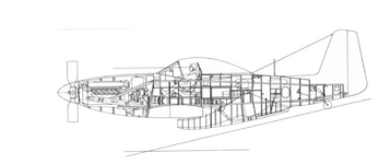
This comparison between the XP-51G and XP-51J shows:
1. the engine installations and cowlings were very different, but the firewall locations were the same
2. aft of the firewalls they were pretty much the same until you get to the tail
3. they added an extra fuselage frame that was approx. 5" long which pushed the rudder hinge line back. The vertical line is the J rudder hinge line. The G rudder hinge line is not shown but you can see how the supporting structure is further forward for the G.
4. the leading edge of the vertical tail is even more upright than before on the J
5. The difference in length between the G and J is split between the cowling and tail. Keep in mind that these comparisons are anchored at the wing spar.
This is because they added an extra fuselage frame at the very end that moved the rudder hinge line further aft. They also greatly enlarged the vertical tail. These features were inherited by the P-51H. Or maybe the J inherited them from the H? I don't know. They were developing all of these Mustang variants, including the P-51D, somewhat concurrently. The contract for the XP-51D (NA-106) came AFTER the contract for the XP-51F (NA-105), after all. There was a war going on and priorities could change at any time.
This comparison between the XP-51G and XP-51J shows:
1. the engine installations and cowlings were very different, but the firewall locations were the same
2. aft of the firewalls they were pretty much the same until you get to the tail
3. they added an extra fuselage frame that was approx. 5" long which pushed the rudder hinge line back. The vertical line is the J rudder hinge line. The G rudder hinge line is not shown but you can see how the supporting structure is further forward for the G.
4. the leading edge of the vertical tail is even more upright than before on the J
5. The difference in length between the G and J is split between the cowling and tail. Keep in mind that these comparisons are anchored at the wing spar.
Attachments
Although the XP-51J had more in common with the P-51H than any other model from the firewall back, the Allison engine installation made it a bit of an odd duck.
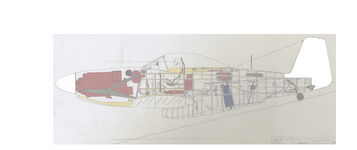
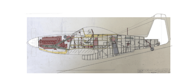
The XP-51J general arrangement drawing shows some notable features:
1. the 2-stage Allison engine installation took up a bit more space than the Merlin installation and the structure was completely different
2. the carb inlet moved to the ventral duct tunnel so the incoming air had to pass through a large rectangular passage under the cockpit floor
3. the Janitrol cockpit heater had to move somewhere and this is not visible in the drawing, but it was tucked under the starboard belly of the Allison engine. Kind of like the stbd engine bay machine gun in an early Allison Mustang. The Allison engine didn't need that space, unlike the Merlin. This seems like a much better location for a heater, gas-fired or not.
4. there was a great big hole in the firewall where the inlet for the 2nd-stage supercharger was located
Attachments
The last step of the journey (ignoring the Twin Mustang, of course) is to go from the XP-51J to the P-51H.
I do not have a good factory drawing of a P-51H. You would think those would be easier to come by. So I used the drawing from the 1/48 Modelsvit P-51H, which is excellent.
I think it is a pretty accurate drawing, based on staring at it and photos of P-51Hs for a few years, now!
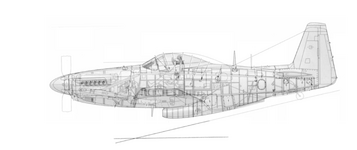
Comparing the XP-51J and P-51H drawings, you see that:
1. the ventral ducting is the same
2. the vertical tails are the same, accounting for the fact that the Modelsvit drawing is of the production tall tail rather than the initial short tail
3. the upper back of the P-51H is raised, so the dorsal fin also had to be raised
4. the firewall was pushed forward on the P-51H by approximately 12". Remember that I am referencing everything to the main wing spar.
5. the cowling was raised in back and flattened out on the P-51H
6. the cowling was a few inches shorter on the P-51H, so the spinner is not a full 12" further forward (it's closer to 8-9")
7. the bubble canopy was reduced in size to be more like a P-51D. Blown canopies were a new technology at this time and the LW Mustang bubble canopies were actually made of two parts glued together. If you look closely in some of the better photos, you can see the joint!
I do not have a good factory drawing of a P-51H. You would think those would be easier to come by. So I used the drawing from the 1/48 Modelsvit P-51H, which is excellent.
I think it is a pretty accurate drawing, based on staring at it and photos of P-51Hs for a few years, now!
Comparing the XP-51J and P-51H drawings, you see that:
1. the ventral ducting is the same
2. the vertical tails are the same, accounting for the fact that the Modelsvit drawing is of the production tall tail rather than the initial short tail
3. the upper back of the P-51H is raised, so the dorsal fin also had to be raised
4. the firewall was pushed forward on the P-51H by approximately 12". Remember that I am referencing everything to the main wing spar.
5. the cowling was raised in back and flattened out on the P-51H
6. the cowling was a few inches shorter on the P-51H, so the spinner is not a full 12" further forward (it's closer to 8-9")
7. the bubble canopy was reduced in size to be more like a P-51D. Blown canopies were a new technology at this time and the LW Mustang bubble canopies were actually made of two parts glued together. If you look closely in some of the better photos, you can see the joint!
Attachments
My real interest in all this was originally just to build models of the XP-51G and J. Based on these comparisons, I do think the most straightforward way to build a XP-51G is to take the top of a P-51D fuselage and the bottom of a P-51H fuselage and glue them together. This is, of course, easier said than done. I'm trying that right now and it is certainly difficult to line things up properly. However, I have also tried starting with a P-51H and then modifying the upper deck and that's pretty hard, too. So like folks have said previously, there's no easy way out! Doesn't mean it can't be done, it's just another challenge!
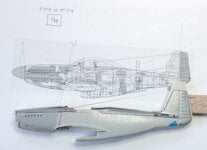
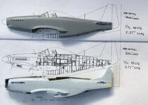
Here's the approach I am taking on the G (first photo). Shorten the P-51H, then graft on the top of the P-51D. The 1/48 Tamiya Mustang has a one-piece top cowling so it is a pretty good candidate. I just hate to cut up a good kit like that if I can avoid it, so I used an old Monogram P-51D. It's cheap, but not such a great choice because it is now THREE pieces you have to attach (the nose is separate).
Still, I think I would take the same approach on a 1/72 model. Here's how the 1/72 RS Models P-51H and recent Airfix P-51D stack up. Please ignore the drawing in this second photo. I made that before I got my hands on the XP-51G general arrangement drawing and this isn't quite right (cowling is too short and tail is too long, by several full-scale inches).
Attachments
One thing that had me puzzled for a while is that while the firewall of the P-51H is clearly ahead of the wing, the firewalls of all other Mustangs intercept the wing.
This is true even on the LW Mustangs, which didn't have the leading edge kink, so their leading edges were further back. So why weren't their firewalls now ahead of the wing?
The reason is because of that change in firewall angle between the P-51D and XP-51F. This made the firewall more vertical and therefore it still intercepted the wing even though the kink was no longer there.
drgondog
Major
I'm in the middle of my Lightweight Mustangs book so not quite at liberty to share everything.One thing that had me puzzled for a while is that while the firewall of the P-51H is clearly ahead of the wing, the firewalls of all other Mustangs intercept the wing.
This is true even on the LW Mustangs, which didn't have the leading edge kink, so their leading edges were further back. So why weren't their firewalls now ahead of the wing?
The reason is because of that change in firewall angle between the P-51D and XP-51F. This made the firewall more vertical and therefore it still intercepted the wing even though the kink was no longer there.
I can however answer some questions for you.
1. NAA changed the FS reference 'FS=0' several times then quit with the XP-51F/G/J & H. The change in FS=0 reference was first caused by the addition of Packard Merlin inst'l. The P-51B FS = 0 at 7.69" aft of Cowl/Spinner. NA-73 thru NA-99 F= 0 at 8"aft
2. With the right combination of drawings you can see that everything aft of the firewall, including location of the 25% chord line remains at FS=99. The Main Spar attach is at FS=104, IIRC the aft spar attach is FS= 143. The tip of the Spinner relative to the 25% chord line remained the same for all allison models, and the same for all Packard models - but very slightly different from each other.
So many parts were same or dimensionally the same from NA-73 through NA-122, with first major changes from upper longeron relationship with aft deck for P-51D.
3. Beginning with the XP-51F, the reference FS=0 was at tip of spinner.
4. The P-51H firewall did not move forward, the wing 25% chord line (and associated spar attach locations) moved aft. The aft fuselage frame assy was lengthened ~ 13", moving the empennage further away from the 25% chrd line, changing some stability derivatives - but necssary to accomodate the 50gal fuselage tank - with no aft cg issues.
5. From Spinner tip to 25% chord line
XP-51 = 133in
P-51B/D = 132.69in
XP-51F = 130.25in
XP-51G/NA-117 = 128.25 This was going into production but lack of fuselage tank forced change to the longer NA-126
XP-51J = 135.25
P-51H - 139.25
From these you can see that the first real 25% chord line changes (visually perceptible on a model) occurred with NA-105B and NA-126. The primary reason was inst'l of 50-gal fuse tank - which is why NA-117 died when AAF reguired the 85gal fuse tank for all post Jan 1 1944 deliveries. The H was accepted because it increased wing fuel to 205gal from 180 in the other LW Mustangs.
You have to be careful on XP-51F drawings. The first NA-105 dated Jan 1943 differed from final April 1943 as the wing changed from 45-100 to the final NACA 66. Interesting (to some) was the change from birdcage to bubble canopy occurred for both NA-106 and NA-105 in the same month.
You brought up a subject, namely mold techniques for canopy. I have only found obscure and unhelpful references to the summer 1943 two piece bubble canopy forned by 'draping' over mold, then moving to molded single piece - do you have a source I could go look at?
Regards,
Bill
Last edited:
When do you expect this book to come out? Can't wait to see it!
Regarding the two piece bubble canopy, I saw the join line in a number of photographs. I don't know anything about the manufacturing methods. I asked John Morgan about it and he confirmed that there was indeed a joint. The photos show that it isn't exactly in the same location on all aircraft. He said that some were shiplap joints and others just butt joints. My guess is that they could get away with it for these experimental aircraft and never would have gone into production like that. The FJ-1 Fury had a similar bubble canopy and it was one piece, so apparently they had worked out the bugs in making larger bubble canopies during that time (the Fury came along not too long after the XP-51F, but things were moving fast).
Regarding the two piece bubble canopy, I saw the join line in a number of photographs. I don't know anything about the manufacturing methods. I asked John Morgan about it and he confirmed that there was indeed a joint. The photos show that it isn't exactly in the same location on all aircraft. He said that some were shiplap joints and others just butt joints. My guess is that they could get away with it for these experimental aircraft and never would have gone into production like that. The FJ-1 Fury had a similar bubble canopy and it was one piece, so apparently they had worked out the bugs in making larger bubble canopies during that time (the Fury came along not too long after the XP-51F, but things were moving fast).
drgondog
Major
I'm about 100% done on research, 50% on deathless prose, pondering what to put in appendices.When do you expect this book to come out? Can't wait to see it!
Regarding the two piece bubble canopy, I saw the join line in a number of photographs. I don't know anything about the manufacturing methods. I asked John Morgan about it and he confirmed that there was indeed a joint. The photos show that it isn't exactly in the same location on all aircraft. He said that some were shiplap joints and others just butt joints. My guess is that they could get away with it for these experimental aircraft and never would have gone into production like that. The FJ-1 Fury had a similar bubble canopy and it was one piece, so apparently they had worked out the bugs in making larger bubble canopies during that time (the Fury came along not too long after the XP-51F, but things were moving fast).
Also trying to figure out self publishing vs publishing house. I dont trust Schiffer and Osprey somehow let a .pdf copy loose to a Russian website tha gleefully permitted free downloads of the Bastard Stepchild.
SaparotRob
Unter Gemeine Geschwader Murmeltier XIII
That pissed me off. Do you have a preferred vendor of BSCOT8AF?I'm about 100% done on research, 50% on deathless prose, pondering what to put in appendices.
Also trying to figure out self publishing vs publishing house. I dont trust Schiffer and Osprey somehow let a .pdf copy loose to a Russian website tha gleefully permitted free downloads of the Bastard Stepchild.
My credit card is out and ready.
Thanks very much folks for a really useful series of messages. Bill I look forward to the book coming out. Eric, I'm convinced by the D-top + H bottom idea, and today I decided to take the plunge. The parts in the photo are only tacked together but the principle is good I think.
Attachments

Users who are viewing this thread
Total: 1 (members: 0, guests: 1)
Similar threads
- Replies
- 0
- Views
- 768