Airfix 1/24 scale Bf109E.....or a bed of thorns

Ad: This forum contains affiliate links to products on Amazon and eBay. More information in Terms and rules

THX H~...:D

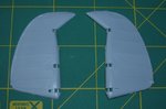
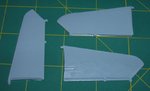
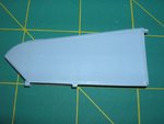
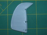
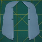
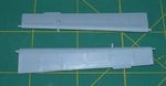
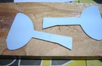
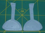
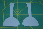
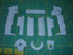
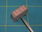
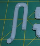
The tail surfaces look good and using of sandpaper is needed when you put halves of these parts together.However these are moulded fully with styrene what makes their weight quite huge. I would suggest removing plastic from inner surfaces to make them lighter.But it is job for more patient modellers.
 

Attachments

  • ster1.jpg
    ster1.jpg
    75.2 KB · Views: 367
  • ster3.jpg
    ster3.jpg
    70.2 KB · Views: 340
  • ster4.jpg
    ster4.jpg
    81.5 KB · Views: 342
  • ster5.jpg
    ster5.jpg
    85.8 KB · Views: 336
  • ster2.jpg
    ster2.jpg
    97.1 KB · Views: 342
THX Gents....:D

Here you are the main landing gear doors.These look good and need a small correction only.There is a lack of partition lines on the outher surfaces.Quite easy to make and I have engraved them without any problem. I have sanded the outer surfaces because there were small cavities at tops.It made them smooth and thinner.The more serious problem are these stamp traces at the inner areas. I have remeved them by scraping and sanding.But I have forgotten about taking a shot.Sorry. What is more one of them wasn't recessed. The easiest way would be using a putty for that and sanding.But the thickness of these parts let me do that easy. Ailerons are OK and need to be sanded a little bit at edges only.
 

Attachments

  • aileron1.jpg
    aileron1.jpg
    69.5 KB · Views: 352
  • doors1b.jpg
    doors1b.jpg
    98.4 KB · Views: 360
  • doors1a.jpg
    doors1a.jpg
    92.7 KB · Views: 354
  • doors1.jpg
    doors1.jpg
    80 KB · Views: 357
Last edited:
Excellent surgery Professor Wojtek! Brought back memories of doing mine. I 'cheated' on the starboard spark plug access panel, and cut it out, scratch-built a new one from plastic card and strip, and positioned it in the open position.
I didn't have a problem with the fit of the main cowling, with the engine installed - I think this is another sign of the age of the moulds. I did have a slight problem, as I remember, with the saddle cowling though, getting the joint aligned properly, as there is very little joining surface, with the edges of the plastic being very thin.
Looking forward to more my friend.
 
THX Terry. :D

Here the engine set. All parts looks nice and it was an easy assembling. The last pic shows the engine assembled without the front part and its cowling .
 

Attachments

  • engin4.jpg
    engin4.jpg
    93.3 KB · Views: 370
  • engin3.jpg
    engin3.jpg
    94.2 KB · Views: 376
  • engin2.jpg
    engin2.jpg
    99.6 KB · Views: 359
  • engin1.jpg
    engin1.jpg
    96.6 KB · Views: 354
Wow........... Wojetk, while I sleep, you make with the magic wand. What a lovely kit and a great start and thanks for the detailed picture progress, this is going to be a build to watch and you'll be have me up at dawn tomorrow looking at the latest update.
 
Thank you guys. :D

You are right Terry the DB engine was an excellent German design. Here the replic painted matt black with an initial silver wash.The front part of the engine with the prop rotary slot has already been painted and glued.
 

Attachments

  • engine2.jpg
    engine2.jpg
    109.3 KB · Views: 379
  • engine2a.jpg
    engine2a.jpg
    115.2 KB · Views: 375
  • engine2b.jpg
    engine2b.jpg
    136.8 KB · Views: 374
THX :)

The farther work on the engine....
 

Attachments

  • engine3.jpg
    engine3.jpg
    108.1 KB · Views: 332
  • engine3a.jpg
    engine3a.jpg
    103.9 KB · Views: 331
Uhumm....;)

Here is the radiator for the engine.According to the kit asembling manual it should be mounted under the engine maquette. Initially I painted it with brassy paint.Later I added black wash.
 

Attachments

  • engine4a.jpg
    engine4a.jpg
    110.4 KB · Views: 356
  • engine4.jpg
    engine4.jpg
    92.6 KB · Views: 348
THX Gents :)

But there appeared a problem with the cooler.The assembling manual shows that the radiator should be fixed to the part that looks like a pipe..I have checked it with pictures and it is incorrect rather.However the pipe should be mounted between right and left row of pistons.To be honest the pipe was more thinner than the one of the kit.Besides joints on the pipe don't fit correctly and I had to make them deeper.As a result the cooler went up a little bit. But I have noticed it when the engine was mounted to the fuselage.

A few pics....
 

Attachments

  • engine4b2.jpg
    engine4b2.jpg
    116.8 KB · Views: 332
  • engine4b.jpg
    engine4b.jpg
    102.5 KB · Views: 335
  • engine4b1.jpg
    engine4b1.jpg
    107.5 KB · Views: 341
  • engine5.jpg
    engine5.jpg
    103.3 KB · Views: 344
  • engine5a.jpg
    engine5a.jpg
    119.6 KB · Views: 343

Users who are viewing this thread

Back