Airframes
Benevolens Magister
Very nice work !
Follow along with the video below to see how to install our site as a web app on your home screen.
Note: This feature may not be available in some browsers.
Ad: This forum contains affiliate links to products on Amazon and eBay. More information in Terms and rules
I undestand it is the dry fit. But you added the white strips for filling the aeras of cockpit sides right?. Looking at your pictures ( especially the second one in the post #19) I've gotten an impression that these white strips were of a rectangle shape. In fact these fillings made by Anglishmen were of a wedge shape. The rails for conopy sliding were fixed to top edges of the fillings. This causes the rail axis is not parallel to the previous edges of the fuselage sides for the US conopy. As a result, the front of the rail is a little bit up than the rear one.
Now i understand what you mean. If you look at the small size pics at post #1 you will see that also my fillings are of a wedge shape as wedge as the shape of the fuselage permitted me. I just followed the lines of the kit. Anyway i got your point, the problem is that if i follow the right way i will cover the small handle(?) at the left side behind the windows.
John

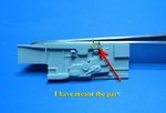
Wojtek, there is no way to get you wrong my friend, the main reason that i post my build is that, to hear opinions, comments and any mistakes to be revealed. At which handle are you referring to? I presume something at the port sidewall of the cockpit but i did not understand! Me by saying (probably wrong term) ''handle'' i was referring to the small oval detail at the port fuselage where the rail ends. If you look at the second pic at the post #19 just below the rear window you will understand. Anyway no worries my friend, my ears are wide open for comments.
") ), a small update...
), a small update...