Great work so far!
Navigation
Install the app
How to install the app on iOS
Follow along with the video below to see how to install our site as a web app on your home screen.
Note: This feature may not be available in some browsers.
More options
You are using an out of date browser. It may not display this or other websites correctly.
You should upgrade or use an alternative browser.
You should upgrade or use an alternative browser.
5" 38 Mark 28 Twin Gun Secondary Battery from Iowa Class Battleships (2 Viewers)
- Thread starter Builder 2010
- Start date
Ad: This forum contains affiliate links to products on Amazon and eBay. More information in Terms and rules
More options
Who Replied?Crimea_River
Marshal
Indeed.
- Thread starter
- #23
Builder 2010
Staff Sergeant
Sure hope I can live up to your expectations.
Spent a lot of time without much to show for it. Most of it was wrestling with the ladder rung prints, both in trying to separate them from the supports and backing piece, and then drilling out the jig to use when mounting them. They are too darn thin... scale, but thin. Removing them was quite painstaking and a bunch failed that had to be repaired with Bondic. There was another problem. I made some very tiny drawing errors that prevented the part from being structurally sound. One small face on the mounting lug was reversed and therefore, didn't print. This lead to the failure of the bolt head to print that was attached to this now-missing face. Also, the rung mounting point was weak and failed many times.
I stopped messing with it and went back to the drawing board, fixed that reversed face, increased the rung diamter by 30% ]and strengthened the mounting point. It's printing now and I'll get them tomorrow.

I aslo tried the drill jig idea and it worked. Only problem was some of the holes were into that chamfer area. I also changed this part too for the next print. I'm using a #57 drill, but a #56 would be better since I had to push too hard to get the lugs to seat and that leads to distortion and breakage.
I also got successful prints of the two mirror-image side access hatches. Last print failed three-out-of-four times due to insufficient support at the lowest corner. When that support failed, the part distorted in that area. I added more support and the four parts were perfect. Even the grab handle formed perfectly.

With the Fulament spring built plate I'm using, I rarely have adhesion failures, but I do get support failures. It is crucial to put a lot of heavy supports at the lowest (first) edges that form. Not only do you want to have a good, solid start to the print, but the lower supports have to support the ever-increasing weight of the part as it's forming. It's all proportional. A small part may look like this rule doesn't apply. Afteral, how much can it weigh? But it's not just gravity you're fighting. There is also suction created due to the perfectly flat surface created betweenl the FEP when the resin layer is curing. The build plate, through the supports, has to break that seal to lift the part so fresh resin can infill beneath the part. I've printed hundreds of parts in the four years I've been at this, and still have support failures. There are guidelines, but there are no hard-fast rules.
As the part forms you can lighten the supports on the upper reaches since the amount of mass is greatly reduced. I also add light supports to all details where removing the heavier supports would destroy the detail you're trying to print when you remove them.
Spent a lot of time without much to show for it. Most of it was wrestling with the ladder rung prints, both in trying to separate them from the supports and backing piece, and then drilling out the jig to use when mounting them. They are too darn thin... scale, but thin. Removing them was quite painstaking and a bunch failed that had to be repaired with Bondic. There was another problem. I made some very tiny drawing errors that prevented the part from being structurally sound. One small face on the mounting lug was reversed and therefore, didn't print. This lead to the failure of the bolt head to print that was attached to this now-missing face. Also, the rung mounting point was weak and failed many times.
I stopped messing with it and went back to the drawing board, fixed that reversed face, increased the rung diamter by 30% ]and strengthened the mounting point. It's printing now and I'll get them tomorrow.
I aslo tried the drill jig idea and it worked. Only problem was some of the holes were into that chamfer area. I also changed this part too for the next print. I'm using a #57 drill, but a #56 would be better since I had to push too hard to get the lugs to seat and that leads to distortion and breakage.
I also got successful prints of the two mirror-image side access hatches. Last print failed three-out-of-four times due to insufficient support at the lowest corner. When that support failed, the part distorted in that area. I added more support and the four parts were perfect. Even the grab handle formed perfectly.
With the Fulament spring built plate I'm using, I rarely have adhesion failures, but I do get support failures. It is crucial to put a lot of heavy supports at the lowest (first) edges that form. Not only do you want to have a good, solid start to the print, but the lower supports have to support the ever-increasing weight of the part as it's forming. It's all proportional. A small part may look like this rule doesn't apply. Afteral, how much can it weigh? But it's not just gravity you're fighting. There is also suction created due to the perfectly flat surface created betweenl the FEP when the resin layer is curing. The build plate, through the supports, has to break that seal to lift the part so fresh resin can infill beneath the part. I've printed hundreds of parts in the four years I've been at this, and still have support failures. There are guidelines, but there are no hard-fast rules.
As the part forms you can lighten the supports on the upper reaches since the amount of mass is greatly reduced. I also add light supports to all details where removing the heavier supports would destroy the detail you're trying to print when you remove them.
- Thread starter
- #25
Builder 2010
Staff Sergeant
I printed the more robust ladder rungs and I'm pleased with the result.

This shot was taken during the removal process. I've found that using the flush cut tweezers thing that MicroMark sells seems to work pretty well in snipping tiny supports. I also used a very sharp #11 blade. The blade only works on parts that ARE NOT post-cured.

And here they all are ready to go under the UV lights for post-curing. In their native state, they were too flexible to be useful. That flexiblility is imparted by the Siraya Tenacious flexible resin in the mix. The extra girth really added survivability to these delicate parts.

I was at the local hobby shop and picked up the scale I-beams and some 5/32 angle stock to build the gun house.
I'm in a highly unusual situation. I am working five projects at the same time. I usually work one at a time, but not now. I have the turret project running concurrently with the Takom 1/35 AH-64D Apache. I thought I'd get the latter completed in time for my modeling club's regional exibition, but probably won't and will enter some of my previously built models instead.
Speaking of the show (in September), I slated to make two 45 minute presentations on the 16" turret project, the title of which is: **"21st Century Modeling: Traditional Skills+3D CAD+3D Printing"** That's project #3.
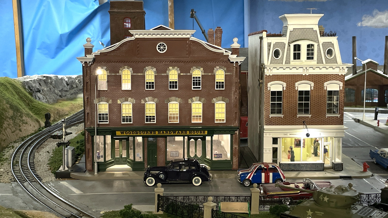
Project #4 is creating a small n-gauge train layout for the window of the Newtown Hardware House in Newtown, PA. This commission job stems from my creation of an O'scale version of this iconic Newtown building that was a hardware store since its inception in 1869. The store's owner was so impressed with the fidelity of the build that he asked if I could do the RR. I just happened to have built such a small layout with the grandsons 12 years ago and will modify this layout for the store. I'm making an n-gauge version of this model. At that size, I can 3D entire walls in one go, unlike this one where I had to have the walls laser cut.
Project #5 is helping a good friend and fabulous modeler, Chris Bowling, refurbish a 1:15 scale model of the NASA Space Shuttle. I'm tasked with creating the artwork for 1:15 scale vinyl wrap that will have the heat resistant tile design. I met Chris through our modeling club and his work is spectacular. We have sort of a mutual admiration society going. I'm not quite as festidious a modeler as Chris, but I experiment more and push the envelope. I'm sort of the R&D department. The model was originally built by North American Rockwell and will be on permanent display at a new air museum in Bowling Green, KY.
So if tend to drop out from one project or another, don't worry, it's just me doing what I do.
This shot was taken during the removal process. I've found that using the flush cut tweezers thing that MicroMark sells seems to work pretty well in snipping tiny supports. I also used a very sharp #11 blade. The blade only works on parts that ARE NOT post-cured.
And here they all are ready to go under the UV lights for post-curing. In their native state, they were too flexible to be useful. That flexiblility is imparted by the Siraya Tenacious flexible resin in the mix. The extra girth really added survivability to these delicate parts.
I was at the local hobby shop and picked up the scale I-beams and some 5/32 angle stock to build the gun house.
I'm in a highly unusual situation. I am working five projects at the same time. I usually work one at a time, but not now. I have the turret project running concurrently with the Takom 1/35 AH-64D Apache. I thought I'd get the latter completed in time for my modeling club's regional exibition, but probably won't and will enter some of my previously built models instead.
Speaking of the show (in September), I slated to make two 45 minute presentations on the 16" turret project, the title of which is: **"21st Century Modeling: Traditional Skills+3D CAD+3D Printing"** That's project #3.
Project #4 is creating a small n-gauge train layout for the window of the Newtown Hardware House in Newtown, PA. This commission job stems from my creation of an O'scale version of this iconic Newtown building that was a hardware store since its inception in 1869. The store's owner was so impressed with the fidelity of the build that he asked if I could do the RR. I just happened to have built such a small layout with the grandsons 12 years ago and will modify this layout for the store. I'm making an n-gauge version of this model. At that size, I can 3D entire walls in one go, unlike this one where I had to have the walls laser cut.

Project #5 is helping a good friend and fabulous modeler, Chris Bowling, refurbish a 1:15 scale model of the NASA Space Shuttle. I'm tasked with creating the artwork for 1:15 scale vinyl wrap that will have the heat resistant tile design. I met Chris through our modeling club and his work is spectacular. We have sort of a mutual admiration society going. I'm not quite as festidious a modeler as Chris, but I experiment more and push the envelope. I'm sort of the R&D department. The model was originally built by North American Rockwell and will be on permanent display at a new air museum in Bowling Green, KY.
So if tend to drop out from one project or another, don't worry, it's just me doing what I do.
BertUS
Senior Airman
I love the way you show us the progress. For now I really likes the drawing and printingsection. It seems Sketchup grows and is e good program to use and simplisticer then SW.
Just a question, did you draw oft parts wich will be on screen perfect, but from the printer to small, thin or so?
Just a question, did you draw oft parts wich will be on screen perfect, but from the printer to small, thin or so?
- Thread starter
- #28
Builder 2010
Staff Sergeant
I tend not to draw things that won't print. I used the word "try" deliberately. For example: I chose to draw the hydraulic piping so it would print with the gun, but the printer had other ideas. From the looks at the failure, it seems like the pipes were never fully attached to their flanges. When they started forming, they didn't hold up. I find that a free standing surface of less than 1/32 (or 1mm) is too thin to be practical in our 1:1 world. You can go thinner, but it better be supported all around for it to survice. Also, free standing levers, while they could print, they would be too frail to stand up to support separation, painting, etc. I usualy try to join them to a surface. Plastic model companies deal with this all the time with injected molded parts.
I got the gun drawing done so it's about as good as I'm going to get it. I had Ryan take a look and he said it would work and was surprised to see it all naked.


With a decent drawing I was able to print it. The barrels are already printed. I had a choice to make of printing the entire gun assembly or print the shield separately. After attempting to install it in my mind, I didn't like how it was going and printed it as a single piece. In actuallity, the shield assembly printed reasonably well. I chose to remove the trunnion pins and will machine them out of aluminum to the .147" diameter on my lathe. I drilled the holes a little deeper to accept them.

Notice the phos-bronze hydraulic lines to the rammer piston. My resin printed ones didn't. It appeared that the pipes were not actually joined to their flanges in the drawing and they failed to form correctly. Better with metal anyway.

The trough that accepts the projectile and cartridge did not form. It was paved over with a resin sheet. Not sure where it was coming from. Drawing that trough was difficult for me, so instead of redrawing and reprinting, I used the Dremel with flexishaft and a spherical diamond-coated burr, and carved the channel back in. These will be partially obscured with a projectile and cartridge load. The back left edge of the curved shield was slightly missing, but was rebuit with Bondic.

Another view of the tail of the gun showing the trough. The trough and the sloped shelf next to it are brass on the rear gun to avoid any sparking.

The real test was how well the gun fit the slide and how well the slide fit the mounts. For the former, I had to open the gun opening much deeper. There was some errant resin growth inside. I tried using an appropriately-sized drill, but it wasn't working well and I was afraid I would break something. I then turned to another diamond burr and ground it out. The diameter of the shield and front of the slide was perfect. The gun was a sliding fit.
As to the fit into the mount, it was perfect!


When painted these will look pretty good. I loved how the gear teeth formed on the elevation gear. Out of the four guns I printed (2 R and 2 L) one pair is good enough to use. I have some more metal works to add. A couple of the handles broke off on the side operating lever. I just thought of using some very thin shim brass to actually line the trough with real metal. I will experiment on one of the reject guns to see if that works.
So folks, WE HAVE GUNS!
I also finally decided to build the model exactly as it is in the ship. With the magazines correctly offset and in the correct deck, it will occupy a display space of about 1' X 1' X 1' and that's really not too big and much smaller than the 16" monster.
Next up will be to design and print the hydraulics and sighting gear that really complicates the turret. Then I'll start working on the Ready Service Room and the projectile/cartridge hoists. I don't have any good references on the structural steel that supports the hanging central column and the hoists attached to it. I did get a properly sized piece of brass tubing that will serve as the central column.
I got the gun drawing done so it's about as good as I'm going to get it. I had Ryan take a look and he said it would work and was surprised to see it all naked.
With a decent drawing I was able to print it. The barrels are already printed. I had a choice to make of printing the entire gun assembly or print the shield separately. After attempting to install it in my mind, I didn't like how it was going and printed it as a single piece. In actuallity, the shield assembly printed reasonably well. I chose to remove the trunnion pins and will machine them out of aluminum to the .147" diameter on my lathe. I drilled the holes a little deeper to accept them.
Notice the phos-bronze hydraulic lines to the rammer piston. My resin printed ones didn't. It appeared that the pipes were not actually joined to their flanges in the drawing and they failed to form correctly. Better with metal anyway.
The trough that accepts the projectile and cartridge did not form. It was paved over with a resin sheet. Not sure where it was coming from. Drawing that trough was difficult for me, so instead of redrawing and reprinting, I used the Dremel with flexishaft and a spherical diamond-coated burr, and carved the channel back in. These will be partially obscured with a projectile and cartridge load. The back left edge of the curved shield was slightly missing, but was rebuit with Bondic.
Another view of the tail of the gun showing the trough. The trough and the sloped shelf next to it are brass on the rear gun to avoid any sparking.
The real test was how well the gun fit the slide and how well the slide fit the mounts. For the former, I had to open the gun opening much deeper. There was some errant resin growth inside. I tried using an appropriately-sized drill, but it wasn't working well and I was afraid I would break something. I then turned to another diamond burr and ground it out. The diameter of the shield and front of the slide was perfect. The gun was a sliding fit.
As to the fit into the mount, it was perfect!
When painted these will look pretty good. I loved how the gear teeth formed on the elevation gear. Out of the four guns I printed (2 R and 2 L) one pair is good enough to use. I have some more metal works to add. A couple of the handles broke off on the side operating lever. I just thought of using some very thin shim brass to actually line the trough with real metal. I will experiment on one of the reject guns to see if that works.
So folks, WE HAVE GUNS!
I also finally decided to build the model exactly as it is in the ship. With the magazines correctly offset and in the correct deck, it will occupy a display space of about 1' X 1' X 1' and that's really not too big and much smaller than the 16" monster.
Next up will be to design and print the hydraulics and sighting gear that really complicates the turret. Then I'll start working on the Ready Service Room and the projectile/cartridge hoists. I don't have any good references on the structural steel that supports the hanging central column and the hoists attached to it. I did get a properly sized piece of brass tubing that will serve as the central column.
Vic Balshaw
Major General
Loving this. 

Lucky13
Forum Mascot
Most excellent work! 

BertUS
Senior Airman
O man, I really like this and the way you describe the whole process
Great work so far!
- Thread starter
- #34
Builder 2010
Staff Sergeant
Thanks, as always.
Finished up with the guns for a while until painting and assembly. Added or fixed the broken levers and handles. I permanently glued the gun mounts to the frame. It's okay to do that now since it makes a stable assembly for further work on all the ancillary equipment. I also got the rammer hydraulic lines in place and replaced the first long one with a more properly shaped one.


I cut out my gun house patterns, applied a light coat of MicroMark Pressure Sensitive Adhesive and stuck them onto a large piece of 0.040" styrene sheet. This represents about 2" in scale, close to the scale 2.5" armor on the gun house. Instead of using the right and left side gun house templates, I just cut one and used it to trace the other side. I then clamped them together and sanded their edges lightly so they identical. When possible, I used the corners and edges of the sheet for at least one of the sides.

Here's a closer look at the gun house side...

All four of the top pieces had to be exactly the same width and the gun slots had to line up. So I used one of them to trace the other three, even though I had drawn them and they equal in the drawing. This eliminated the slight variations that would crop up depending on which side of the line I was cutting. I got most of them cut out today. I tried the sides onto the 3D printed curved back wall and was rewarded that the corner rabbett that I printed perfectly blended with the styrene sides. I don't have any drawing stuck onto the side piece that I traced, but I will need the location of the side access hatch. For the actual hatch cuts I will trace the real one. I'm also going to located and drill all the holes for the foot rungs while it's all in the flat. I have to do some finish sanding on the edges and the gun slots. I also have to sand bevels on the mating surfaces of the angle pieces so they mate properly. All joints will have 3/16" styrene angle as does the prototype.

Meanwhile, while printing parts for another project a calamity happened. After a major print failure... and I mean "major" in the sense that the only thing that printed on the build plate was the base raft. All the rest was a series of variously shaped blobs stuck to the FEP teflon film at the resin vat's bottom.

I was able to remove the crap on the bottom without destroying the FEP (I hope), then I looked at the LCD protective plate and saw a series of bad cracks propagating across the LCD. I thought it was the tempered glass protective plate that I bought to protect the delicate LCD below. But when I removed the undamaged cover plate, I realized that the cracks were in the LCD itself. I did a light test and it failed miserably. Half the screen was disfunctional. The cracks are quite obvious in this image. I need to understand why the print failure happened in the first place. I've tried printing this part three times with not very good success before the complete mess that this attempt was.

I ordered a new screen from Amazon which will be delivered soon and I'll install it on Monday and hopefully, all my projects will continue uninterrupted. Elegoo has a new machine out that uses a Texas Instruments DLP chip. This device has been around for a long time and since it projects its pixel image though lenses and mirrors to the resin vat and doesn't get any physical pressure from the z-axis lead screw and stepper motor. It was the plate attempting to compress those hardening lumps on the vat's bottom that caused the damage to the LCD screen. I think my next printer is going to that technology. So this summer I've added a new motherboard, new touch screen and now a new LCD screen. Wish me luck. I can continue to build the sheet work without the printer running, but I really need it.
I found out from Ryan today that the splinter deck is only 30" high, made up a massive series of square compartments with manholes separating each of them. I will only be showing a little bit of that detail. It's only function is too isolate the magazines below from any shrapnal that may attempt to get there from action above. I don't believe any of the Iowas saw any action that involved this structure.
Finished up with the guns for a while until painting and assembly. Added or fixed the broken levers and handles. I permanently glued the gun mounts to the frame. It's okay to do that now since it makes a stable assembly for further work on all the ancillary equipment. I also got the rammer hydraulic lines in place and replaced the first long one with a more properly shaped one.
I cut out my gun house patterns, applied a light coat of MicroMark Pressure Sensitive Adhesive and stuck them onto a large piece of 0.040" styrene sheet. This represents about 2" in scale, close to the scale 2.5" armor on the gun house. Instead of using the right and left side gun house templates, I just cut one and used it to trace the other side. I then clamped them together and sanded their edges lightly so they identical. When possible, I used the corners and edges of the sheet for at least one of the sides.
Here's a closer look at the gun house side...
All four of the top pieces had to be exactly the same width and the gun slots had to line up. So I used one of them to trace the other three, even though I had drawn them and they equal in the drawing. This eliminated the slight variations that would crop up depending on which side of the line I was cutting. I got most of them cut out today. I tried the sides onto the 3D printed curved back wall and was rewarded that the corner rabbett that I printed perfectly blended with the styrene sides. I don't have any drawing stuck onto the side piece that I traced, but I will need the location of the side access hatch. For the actual hatch cuts I will trace the real one. I'm also going to located and drill all the holes for the foot rungs while it's all in the flat. I have to do some finish sanding on the edges and the gun slots. I also have to sand bevels on the mating surfaces of the angle pieces so they mate properly. All joints will have 3/16" styrene angle as does the prototype.
Meanwhile, while printing parts for another project a calamity happened. After a major print failure... and I mean "major" in the sense that the only thing that printed on the build plate was the base raft. All the rest was a series of variously shaped blobs stuck to the FEP teflon film at the resin vat's bottom.
I was able to remove the crap on the bottom without destroying the FEP (I hope), then I looked at the LCD protective plate and saw a series of bad cracks propagating across the LCD. I thought it was the tempered glass protective plate that I bought to protect the delicate LCD below. But when I removed the undamaged cover plate, I realized that the cracks were in the LCD itself. I did a light test and it failed miserably. Half the screen was disfunctional. The cracks are quite obvious in this image. I need to understand why the print failure happened in the first place. I've tried printing this part three times with not very good success before the complete mess that this attempt was.
I ordered a new screen from Amazon which will be delivered soon and I'll install it on Monday and hopefully, all my projects will continue uninterrupted. Elegoo has a new machine out that uses a Texas Instruments DLP chip. This device has been around for a long time and since it projects its pixel image though lenses and mirrors to the resin vat and doesn't get any physical pressure from the z-axis lead screw and stepper motor. It was the plate attempting to compress those hardening lumps on the vat's bottom that caused the damage to the LCD screen. I think my next printer is going to that technology. So this summer I've added a new motherboard, new touch screen and now a new LCD screen. Wish me luck. I can continue to build the sheet work without the printer running, but I really need it.
I found out from Ryan today that the splinter deck is only 30" high, made up a massive series of square compartments with manholes separating each of them. I will only be showing a little bit of that detail. It's only function is too isolate the magazines below from any shrapnal that may attempt to get there from action above. I don't believe any of the Iowas saw any action that involved this structure.
BertUS
Senior Airman
Ouch, bad timing of your screen, something hit the screen?
Till now my Elegoo is good for me, but now I'm a bit worried about the parts .
About your work, looks great, but maybe a bit to high in the exposure time? See some little things it looks like you can lowered your ET with a few 0.1 secs
Till now my Elegoo is good for me, but now I'm a bit worried about the parts .
About your work, looks great, but maybe a bit to high in the exposure time? See some little things it looks like you can lowered your ET with a few 0.1 secs
Excellent work so far!
- Thread starter
- #38
Builder 2010
Staff Sergeant
Thanks for the kind words. The plate was pressing against the elevated pile of curing resin mess stuck to the FEP. That caused the breakage. I will try shortening the exposure. What was the clue that told you I should do that?
I spent almost my whole day on the drawing board (well... virtual drawing board). I'm working on several fronts at the same time. Today's work centered on figuring just what kind of cutaway will be needed to show the magazine buried three decks down, while showing some of the intervening spaces. It's not easy and construction will also be a challenge. I also scoped out the wooden base and the plexiglass case. The base will require some lead time so I'll have to get that constructed earlier than one might think. My last base was done by a dear old friend who lives in Albuquerque. He was the bass player in my band and an exceptional woodworker. I'm not sure I want to task him to build another. He's in the process of scratch-building a stand up double bass. Just to clamp the skins requires 54 screw clamps which he just started constructing from scratch also. He's just as passionate about what he does as I am. (or obsessed...depending who you ask.)
There will be lighting to illuminate the shadowed areas. There will aslo be compartments under gun ready service room. The main deck will be planked. There will be no furnishings on the intermediate decks. I think it's pretty neat that V-Ray renders materials that are loaded from my older rendering engine, Podium. I renders much faster than Podium for these test runs.a

It's one thing to cut openings in a SketchUp drawing. It's quite another to cut them in styrene assemblies. In some cases the former is easier, but in others the latter is.
Before I could start gluing together the turret parts cut yesterday, I had to do a few more design steps. I wanted to cut the opennings for the side access hatches and telescopes while still in the flat. I also want to drill for the foot rungs. I also located the officer's hatch on that small flat roof piece. I was able to cut one hatch opening and clean it up. The printed part fits nicely once I spent some time with needle files to finalize the shape. The hatch drops into the opening and the hinges sit on the surface. If I want to open one of these, I'll have to reprint with a different hinge orientation.
BTW: In handling the hatch, the handhold broke off. I'm going to be replacing a lot of these with 0.020 wire.

Here's a closer look at each.
The left side with the hatch out of the opening.

If I would have planned ahead a bit, I would have included these details in the patterns I used yesterday. 20/20 hindsight. "If my foresight was as good as my hindsight, I'd be better by a damn sight!"
Here's the next pattern with the telescopes for the left side. The left side has two openings: the forward one is for the pointer's position, and the rear for the sight checker. The sight checker uses that telescope mostly for training purposes to evaluate how well the pointer and trainer and managing their positions. I will be 3D printing the hoods for these telescopes. Their flanges go around the perimeter of these openings.

And here's the officer's hatch opening. I'm going to fabricate the counter-balance cylinder out of metal.

There's one more series of parts that's required in gun house construction; There are flat shield on each side of the curved gun shields that seal the curved surface from environmental incursions especially seawater. The curve of the shield covers the curved gun shield. There are two per gun side and then a bottom piece to tie it together. The upper edge is connected to the turret roof.

I used the gun shield in SketchUp in a sectioned drawing to capture both the curve size and position AND the interface with the roof. I can be pretty sure that this works since all the prints were produced from the same drawing. While there's some minor size change in the printing process, it's really insignificant.
Here's an interesting shot of refitting the armor on a 5" turret when refitting the Iowa in the 1980s. Based on this picture, I need to slightly change the lower left corner of the telescope opening. It's not a curve, it's just an angular cut. In this image the guns (without barrels) are fully elevated. Really shows how the gun house fastenes to the main frame. Also good views of how the pointer's machinery is fastened to the frame.

I spent almost my whole day on the drawing board (well... virtual drawing board). I'm working on several fronts at the same time. Today's work centered on figuring just what kind of cutaway will be needed to show the magazine buried three decks down, while showing some of the intervening spaces. It's not easy and construction will also be a challenge. I also scoped out the wooden base and the plexiglass case. The base will require some lead time so I'll have to get that constructed earlier than one might think. My last base was done by a dear old friend who lives in Albuquerque. He was the bass player in my band and an exceptional woodworker. I'm not sure I want to task him to build another. He's in the process of scratch-building a stand up double bass. Just to clamp the skins requires 54 screw clamps which he just started constructing from scratch also. He's just as passionate about what he does as I am. (or obsessed...depending who you ask.)
There will be lighting to illuminate the shadowed areas. There will aslo be compartments under gun ready service room. The main deck will be planked. There will be no furnishings on the intermediate decks. I think it's pretty neat that V-Ray renders materials that are loaded from my older rendering engine, Podium. I renders much faster than Podium for these test runs.a
It's one thing to cut openings in a SketchUp drawing. It's quite another to cut them in styrene assemblies. In some cases the former is easier, but in others the latter is.
Before I could start gluing together the turret parts cut yesterday, I had to do a few more design steps. I wanted to cut the opennings for the side access hatches and telescopes while still in the flat. I also want to drill for the foot rungs. I also located the officer's hatch on that small flat roof piece. I was able to cut one hatch opening and clean it up. The printed part fits nicely once I spent some time with needle files to finalize the shape. The hatch drops into the opening and the hinges sit on the surface. If I want to open one of these, I'll have to reprint with a different hinge orientation.
BTW: In handling the hatch, the handhold broke off. I'm going to be replacing a lot of these with 0.020 wire.
Here's a closer look at each.
The left side with the hatch out of the opening.
If I would have planned ahead a bit, I would have included these details in the patterns I used yesterday. 20/20 hindsight. "If my foresight was as good as my hindsight, I'd be better by a damn sight!"
Here's the next pattern with the telescopes for the left side. The left side has two openings: the forward one is for the pointer's position, and the rear for the sight checker. The sight checker uses that telescope mostly for training purposes to evaluate how well the pointer and trainer and managing their positions. I will be 3D printing the hoods for these telescopes. Their flanges go around the perimeter of these openings.
And here's the officer's hatch opening. I'm going to fabricate the counter-balance cylinder out of metal.
There's one more series of parts that's required in gun house construction; There are flat shield on each side of the curved gun shields that seal the curved surface from environmental incursions especially seawater. The curve of the shield covers the curved gun shield. There are two per gun side and then a bottom piece to tie it together. The upper edge is connected to the turret roof.
I used the gun shield in SketchUp in a sectioned drawing to capture both the curve size and position AND the interface with the roof. I can be pretty sure that this works since all the prints were produced from the same drawing. While there's some minor size change in the printing process, it's really insignificant.
Here's an interesting shot of refitting the armor on a 5" turret when refitting the Iowa in the 1980s. Based on this picture, I need to slightly change the lower left corner of the telescope opening. It's not a curve, it's just an angular cut. In this image the guns (without barrels) are fully elevated. Really shows how the gun house fastenes to the main frame. Also good views of how the pointer's machinery is fastened to the frame.
- Thread starter
- #40
Builder 2010
Staff Sergeant
I'm giving Ryan a choice of how to display the innards of the gun house. My first approach would be a cutaway, but while not to difficult to execute, it doesn't show all that much unless you turn it into Swiss Cheese. Ryan just texted me. It will be the cutaway version which follows the theme of the 16" project.

The second approach could mimic yesterday's photo showing the entire armored casing in the air above the open gun house. This would show almost everything, but would have to be suspended above and it would raise the enclosure height. I could use acrylic rods to support. Lighting would require some visible cabling. In order to raise the casing, the guns need to be elevated, as they are in the photo.

The last is the most elegant and also the most challenging: making the forward parts of the gun house out of clear acrylic. I would leave the curved wall as it is. While I have clear resin, optically it wouldn't be very good and not any value. Acrylic is very clear and shows no distortion. Gluing it together so it really clean is the first challenge. The second is cutting out the small parts with true and square edges.

So I'm also asking all of you. Which do you prefer?
I finished cutting out all the casing parts and trued up all the edges. I cut the telescope holes in the right and left sides, the ofc's hatch opening, and the remaining access hatch opening. I clamped both angled face pieces together so I could finish shape the gun slots so they aligned perfectly.
To cut the telescope holes, I drilled a series of small holes through the drawing, and then used a larger drill to make nice rounded corners.

Here's all the finished parts ready to be assembled.
 s
s
Since I don't know which version Ryan will pick, I did some future planning... While all the casing parts were in the flat, and they're all accurate, I clamped them to a nice piece of 0.080" acrylic that I had laying around and traced all these parts so I'm ready to cut them out if we go that way. If fact, regardless of Ryan's choice I may cut out all those parts and see how well I can finish them. Having it clear would be pretty neat. You can barely see the scribed lines, but they're there. Now that I know Ryan's choice, I'm going to try and construct this version anyway since I've kind of wrecked that part of the acrylic with my scribed layout lines.

I also went at the back of the curved wall and removed that lump. I used a cutting disk to remove most of the stock and then my micro-power sander to finish. I may add some filler to hide all the tool marks.

With the acrylic in the wings, I can continue to construct the regular casing. I won't do the cutaway until after it's built if i go that route, so I won't be getting too far out over my skis.
My new LCD panel arrives today and I've already stripped the old one out of the machine in anticipation. I hope it comes with a new under class plate since I cracked it a bit getting it out of it's depression. It too is held with adhesive stirps. Should be running next week. It has to be running next week. It's on the critical path of two major projects.
Y'all have a nice weekend!
The second approach could mimic yesterday's photo showing the entire armored casing in the air above the open gun house. This would show almost everything, but would have to be suspended above and it would raise the enclosure height. I could use acrylic rods to support. Lighting would require some visible cabling. In order to raise the casing, the guns need to be elevated, as they are in the photo.
The last is the most elegant and also the most challenging: making the forward parts of the gun house out of clear acrylic. I would leave the curved wall as it is. While I have clear resin, optically it wouldn't be very good and not any value. Acrylic is very clear and shows no distortion. Gluing it together so it really clean is the first challenge. The second is cutting out the small parts with true and square edges.
So I'm also asking all of you. Which do you prefer?
I finished cutting out all the casing parts and trued up all the edges. I cut the telescope holes in the right and left sides, the ofc's hatch opening, and the remaining access hatch opening. I clamped both angled face pieces together so I could finish shape the gun slots so they aligned perfectly.
To cut the telescope holes, I drilled a series of small holes through the drawing, and then used a larger drill to make nice rounded corners.
Here's all the finished parts ready to be assembled.
Since I don't know which version Ryan will pick, I did some future planning... While all the casing parts were in the flat, and they're all accurate, I clamped them to a nice piece of 0.080" acrylic that I had laying around and traced all these parts so I'm ready to cut them out if we go that way. If fact, regardless of Ryan's choice I may cut out all those parts and see how well I can finish them. Having it clear would be pretty neat. You can barely see the scribed lines, but they're there. Now that I know Ryan's choice, I'm going to try and construct this version anyway since I've kind of wrecked that part of the acrylic with my scribed layout lines.
I also went at the back of the curved wall and removed that lump. I used a cutting disk to remove most of the stock and then my micro-power sander to finish. I may add some filler to hide all the tool marks.
With the acrylic in the wings, I can continue to construct the regular casing. I won't do the cutaway until after it's built if i go that route, so I won't be getting too far out over my skis.
My new LCD panel arrives today and I've already stripped the old one out of the machine in anticipation. I hope it comes with a new under class plate since I cracked it a bit getting it out of it's depression. It too is held with adhesive stirps. Should be running next week. It has to be running next week. It's on the critical path of two major projects.
Y'all have a nice weekend!
Last edited: