Super Detailing S.E.5 Guillow's model

Ad: This forum contains affiliate links to products on Amazon and eBay. More information in Terms and rules

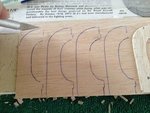
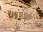
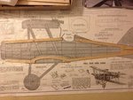
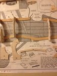
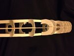
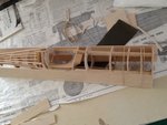
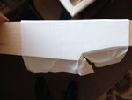
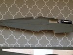
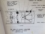
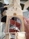
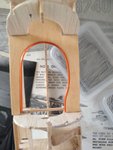
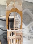
The original profile from the Guillow's kit has the front nose tapered more than what the full sized S.E.5 has. The real aircraft nose is more of a "boxy" squared-on shape. This means I had to lower the bottom keel to compensate for this. The last photo shows the original full sized aircraft with its "boxy" nose. The first picture shows the lower keel in its original position. The following picture shows how I lowered it just a little bit, but enough to make a difference such that I had to cut out new enlarged front-end formers. The kit also supplied a plastic radiator. I placed the completed one that I made from scratch to show the difference not only in detail, but in size to allow it to fit the enlarged front end. On the radiator that I scratch built and detailed, you'll see what appears to be a "flap" on the lower end This will be tucked under the fuselage when installed. The cutout is for the radiator stump drain.
 

Attachments

  • SE5.jpg
    SE5.jpg
    32.4 KB · Views: 99
  • SE52.jpg
    SE52.jpg
    34.3 KB · Views: 88
  • SE5 3.jpg
    SE5 3.jpg
    31.2 KB · Views: 99
  • SE5 240.JPG
    SE5 240.JPG
    276.6 KB · Views: 103
  • SE5 139.JPG
    SE5 139.JPG
    126.1 KB · Views: 110
Last edited:
Thank you Gnomey. It's much appreciated. I'm working as of this writing to locate and file the remaining pictures to get them ready for this build thread. I'm "only" up to over 350 pictures.......
 
Good evening gentlemen,
I would like to illustrate my ideas in pictorial form. To reiterate: in the first picture, I've just lowered the bottom keel to better suit the profile of the model to resemble a more "boxy" profile of the real aircraft as exemplified in the second picture. Next, I had to make up and cut out new enlarged formers to fit into what is now an enlarged space between the upper and lower keels. Third picture illustrates the construction that has commenced. I'm now following the original instructions that came with the kit. Only difference is that I'm now using enlarged formers at the front end of the fuselage. For the next stage, I've eliminated several formers around the cockpit area. When reviewing photographs of the interiors, it struck me that many of the formers and details that went into the kit would have to be either cut away or eliminated altogether.
 

Attachments

  • SE52.jpg
    SE52.jpg
    34.3 KB · Views: 63
  • SE5 93.JPG
    SE5 93.JPG
    293.3 KB · Views: 77
  • SE5 3.jpg
    SE5 3.jpg
    31.2 KB · Views: 68
  • SE5 12.jpg
    SE5 12.jpg
    38.6 KB · Views: 70
  • SE5 6.jpg
    SE5 6.jpg
    33.6 KB · Views: 66
Here, I have shown the next stage of construction. Basically, I've lowered the bottom keel to better reflect the more "boxy" squred-on appearance of the nose profile as seen on the real aircraft. With the bottom keel lowered, there is now more space between the upper and lower keel members which means I'll have to fabricate and cut out larger formers to fit in. At this point, I'm following the instructions as laid out from the kit. Only difference is I'm now using larger formers on the front nose from the pilot's cockpit forward. Finally, the last picture shows I've left out a lot of wooden formers and basically left only the larger longerons (large stringers) about midway between the formers.
 

Attachments

  • SE52.jpg
    SE52.jpg
    34.3 KB · Views: 43
  • SE5 3.jpg
    SE5 3.jpg
    31.2 KB · Views: 46
  • SE5 12.jpg
    SE5 12.jpg
    38.6 KB · Views: 60
  • SE5 6.jpg
    SE5 6.jpg
    33.6 KB · Views: 58
Here, this is what I have of the skeletal framework of the wooden fuselage. As you can see, there really isn't much left between the tail and nose. The cockpit area is basically devoid of almost all wood. The only place where I'll be adding the stringers will be on the back decking behind the pilot's cockpit.
 

Attachments

  • SE5 7.jpg
    SE5 7.jpg
    17.5 KB · Views: 63
  • SE5 14.jpg
    SE5 14.jpg
    15.2 KB · Views: 58
Here I am getting ahead of myself to reveal what my plans are for the model. As you can see, there is a large sheet of balsa covering the whole lower part of the fuselage. This will add tremendous strength and at the same time fill in for the missing stringers as well as giving the fuselage shape.
 

Attachments

  • SE5 30.jpg
    SE5 30.jpg
    173.1 KB · Views: 70
  • SE5 51.jpg
    SE5 51.jpg
    255.8 KB · Views: 69
Now I begin the slow finalizing process of ensuring the purpose of the balsa sheet. I noticed that only in the cockpit interior area, does one see that the fabric of the real aircraft is more of a light almost whitish color while at the same time and location on the outside, the same fabric is painted olive drab. So, it's with this in mind, I covered only a small section of the balsa sheeting where the cockpit interior will be seen once the model is completed. The last photo shows exactly my goal. As you can see, the balsa sheeting is serving its purpose of covering the whole lower portion of the fuselage as well as preserving the boxy squared-on appearance of the original full sized aircraft. **Special note, the lower balsa sheeting will be one of the last items installed permanently as I have to have access to the cockpit interior first.
 

Attachments

  • SE5 162.jpg
    SE5 162.jpg
    156.6 KB · Views: 81
  • SE5 164.jpg
    SE5 164.jpg
    256.8 KB · Views: 81
  • SE5 165.JPG
    SE5 165.JPG
    219.6 KB · Views: 79
Here, this is a photo of the full sized S.E.5 that I personally took while visiting the RAF in Hendon, London about 35 years ago. You can easily compare this picture with the images from the previous post and determine what my goals are to achieve as close replication as possible.
 

Attachments

  • SE5 18.jpg
    SE5 18.jpg
    37.2 KB · Views: 70
Parsi, Crimea, Wurger and other gentlemen,
I thank you very much for your observation and compliments. They're much appreciated.
 
Humble beginning. Small apartment but large in imagination.
 

Attachments

  • IMG_4986.JPG
    IMG_4986.JPG
    51.9 KB · Views: 54
  • SE5 60.JPG
    SE5 60.JPG
    364.7 KB · Views: 66
The model fuselage frame is ready for cockpit interior detailing. A bit of "research," using a combination of my own photos in color and b+w, as well as from detailed drawings and an advertisement illustrates what steps I need to perform and in which order. At this point, I have used my own "mantra" of ** working from the inside out.*** This means that I must detail whatever portions of the interior that are difficult to access such as the floor, rudder bar, and instrument dials first, then slowly work my way up and out of the cockpit. I will start with the basics of laying out the foundations for the detailing by first concentrating on the mid-support structure followed by the main instrument panel. Since the balsa sheets have not been glued in place, leaving the sides exposed, I can still have access to the lower portion of the interior to work on rudder bar, control cables, the pilot's seat and more.
 

Attachments

  • SE5 28.jpg
    SE5 28.jpg
    286.8 KB · Views: 85
  • SE5 29.jpg
    SE5 29.jpg
    179.5 KB · Views: 88
  • SE5 33.jpg
    SE5 33.jpg
    216.6 KB · Views: 87
Among other things in the cockpit that stood out to me was the wood paneling that lined up inside the interior. It almost resembles that of a parlor in one's home. A reflection of architectual design of that time period. So I said to myself, "Well, if he must do combat in the freezing air, he might as well do combat in style." Only things missing would be his dinner jacket, a cup of tea and pipe.
 

Attachments

  • SE5 32.jpg
    SE5 32.jpg
    237 KB · Views: 71
  • SE5 79.JPG
    SE5 79.JPG
    229.8 KB · Views: 82
The mid-level support structure was cut from basswood as I figured that this type of wood is light in color and when stained with a light "peach pecan" color, really makes it look nice. I used copper wire around the cut out to the mid-level support. I had to carefully measure the dimensions within the confines of the cockpit interior and cut the wood to size and shape. I should point out that I took many "artistic licenses" here during the build to help bring out the details through contrast in colors, adding a bit of "bling' here and there to help make each detail of the model really stand out.
 

Attachments

  • SE5 34.JPG
    SE5 34.JPG
    257.6 KB · Views: 72
  • SE5 22.JPG
    SE5 22.JPG
    261 KB · Views: 66
  • SE5 27.JPG
    SE5 27.JPG
    209.2 KB · Views: 70
Next, to get the special effect of metal surrounding the mid-level cut out, I cut a thin strip of black electrical tape. Why electrical tape? It can be pulled to stretch out (just a little bit) & is very flexible around compound curves as you can see. I first practiced this technique on a piece of scrap basswood cut out. Then implemented my technique onto the final piece itself.
 

Attachments

  • SE5 23.JPG
    SE5 23.JPG
    319.4 KB · Views: 52
  • SE5 24.jpg
    SE5 24.jpg
    176 KB · Views: 65
  • SE5 25.jpg
    SE5 25.jpg
    233.2 KB · Views: 68
  • SE5 26.JPG
    SE5 26.JPG
    242.7 KB · Views: 68

Users who are viewing this thread

Back