special ed
1st Sergeant
- 4,867
- May 13, 2018
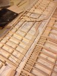
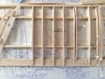
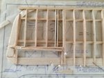
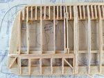
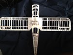
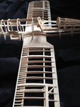
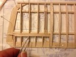
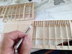
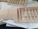
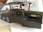
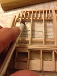
An excellent build.
Follow along with the video below to see how to install our site as a web app on your home screen.
Note: This feature may not be available in some browsers.
Ad: This forum contains affiliate links to products on Amazon and eBay. More information in Terms and rules


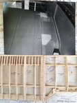
 and also keep it clean) and ready to continue doing your magic.
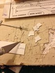
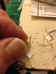
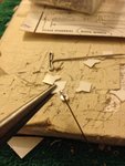
 ... Because us modelers tend to "spread out" as our build progresses, I'm sure my scraps of balsa, tools, bits of paper, model plans, left over frames and more have been slowly taking over his tool shed.......